Definitions [34]
Define a wavefront.
Wavefront is defined as the locus of all the points in space that reach a particular distance by a propagating wave at the same instant.
A wave front is defined as a surface of constant phase.
The branch of optics that considers light as a wave which can bend around objects, diffract and interfere, etc. is called wave optics.
Coupled time-varying electric and magnetic fields that propagate in space are called electromagnetic waves.
The phenomenon that is based on the fact that light waves are transverse electromagnetic waves is called polarisation.
The branch of optics that is based on rectilinear propagation of light and deals with mirrors, lenses, reflection, refraction, etc. is called ray optics.
When the source of light is linear and all the points equidistant from the source lie on a cylinder, the wavefront which is cylindrical in shape is called a cylindrical wavefront.
When the source of light is a point source, the wavefront which is a sphere with the centre as the source is called a spherical wavefront.
When a point source or linear source of light is at very large distance and a small portion of the spherical or cylindrical wavefront appears to be plane, such a wavefront is called a plane wavefront.
The secondary light waves emitted in all directions by each point on a wavefront, which travel with the speed of light in the medium, are called wavelets.
The speed with which the wavefront moves outwards from the source is called the speed of wave.
The locus of all those particles which are vibrating in the same phase at any instant is called a wavefront; thus a wavefront is a surface of constant phase.
The plane in which E vibrates/oscillates is known as the plane of vibration.
A thin film of ultramicroscopic crystals used to produce plane polarised light is called a polaroid.
When the plane of vibration of a wave is changed randomly in very short intervals of time, such waves are called unpolarised waves.
The plane in which vibrations are present is called the plane of polarisation.
The phenomenon of restriction of the vibration of light waves in a particular plane perpendicular to the direction of wave motion is called polarisation of light.
or
The phenomenon of confining the vibrations of the electric vector to a particular direction perpendicular to the direction of propagation of light is called Polarization.
When the displacement of the particle is perpendicular to the direction of propagation of the wave, then it is said to be transverse wave.
The wave in which the vibration of electric field vectors are confined in one plane and parallel to one unique direction is called linearly polarised wave; it is also referred to as plane polarised wave.
The points of minimum intensity in the regions of superposition of waves are said to be in destructive interference.
The phenomenon that occurs when two waves meet while travelling along the same medium is called wave interference.
The phenomenon of redistribution of energy on account of superposition of light waves from two coherent sources is called interference of light.
The points of maximum intensity in the regions of superposition of waves are said to be in constructive interference.
The bending of light near the edge of an obstacle or slit and spreading into the region of geometrical shadow is called diffraction of light.
The type of diffraction that occurs when the source and the observation screen are far away (effectively at infinite distance) from the diffracting object and fringes are not sharp and well-defined is called Fraunhofer diffraction.
The type of diffraction that occurs when the source or screen is at a finite distance from the diffracting object and fringes are not sharp and well-defined is called Fresnel diffraction.
The reciprocal of the least angular separation between the objects that are just resolved is called the resolving power of the telescope.
The quantity μ sin θ, where μμ is the refractive index of the medium between the object and the objective, is called the numerical aperture (N.A.) of the objective of the microscope.
The ability of an optical instrument to produce distinctly separate images of two objects very close to each other is called the resolving power of the instrument.
The minimum distance of separation between two objects when they can be observed as separate by an optical instrument is called the limit of resolution of that instrument.
The reciprocal of the limit of resolution is called its resolving power.
When the separation between the central maxima of two objects is less than the distance between the central maximum and the first minimum of any of the two objects, the images are said to be 'not resolved' or unresolved.
When the separation between the central maxima of the two objects is just equal to the distance between the central maximum and first minimum of any of the two objects, the images are said to be just resolved.
When the separation between the central maxima of two objects is greater than the distance between the central maximum and first minimum of any of the two objects, the images are said to be well resolved.
The condition where the images of two point objects close to each other are regarded as resolved (separated), if the central maximum of one falls on the first minimum of the other, is called Rayleigh's criterion for resolution.
Formulae [8]
I = I1 + I2 + 2\[\sqrt {I_1I_2}\] ⋅ cos ϕ
When I1 = I2 = I0:
I = \[2I_0(1+\cos\phi)=4I_0\cos^2\left(\frac{\phi}{2}\right)\]
\[\frac{I_{\max}}{I_{\min}}=\left(\frac{a_1+a_2}{a_1-a_2}\right)^2=\left(\frac{\sqrt{I_1}+\sqrt{I_2}}{\sqrt{I_1}-\sqrt{I_2}}\right)^2\]
When two waves of amplitudes a1 and a2 interfere at a point where phase difference is ϕ, the resultant amplitude is:
\[A^2=a_1^2+a_2^2+2a_1a_2\cos\phi\]
R.P. = \[\frac{1}{d\theta}=\frac{D}{1.22\lambda}\]
R.P. = \[\frac {1}{\text {Limit of resolution}}\]
R.P. = \[\frac {1}{d}\] = \[\frac{2\mu\sin\theta}{\lambda}\]
where μ sin θ is the Numerical Aperture (N.A.) of the objective.
Smallest angular separation dθdθ (Circular aperture):
\[d\theta=\frac{1.22\lambda}{D}\]
where D is the aperture (diameter) of objective of the telescope.
Smallest angular separation (Rectangular aperture):
\[d\theta=\frac{d}{D}\]
where d is slit separation and D is distance.
Limit of resolution (self-luminous objects):
d = \[\frac{1.22\lambda}{2\sin\theta}=\frac{0.61\lambda}{\sin\theta}\]
Limit of resolution (objects illuminated by light of wavelength λ):
d = \[\frac{\lambda}{2\sin\theta}\]
If a liquid of refractive index μμ is between object and objective:
d = \[\frac{\lambda}{2\mu\sin\theta}\]
where θθ is the angle subtended by an object at the objective.
Theorems and Laws [4]
Huygens' Principle states that:
- Each point on a wavefront acts as a secondary source of light emitting secondary light waves called wavelets in all directions.
- These wavelets travel with the speed of light in the medium.
- The new wavefront can be obtained by taking the envelope of these secondary wavelets travelling in the forward direction.
- The wavelets travelling in the backward direction are ineffective.
Additional Points:
- Huygens' principle is a geometrical construction which gives the shape of the wavefront at any time and allows us to determine the shape of the wavefront at a later time.
- It also tells how a wavefront propagates through a medium.
- The energy of the wave travels in a direction perpendicular to the wavefront.
Statement: When plane polarised light is incident on an analyser, the resultant intensity of light transmitted from the analyser varies directly as the square of the cosine of the angle between the plane of transmission axis of the analyser and polariser.
Formula:
Where:
- I0 = intensity of plane polarised light
- I = intensity of transmitted light from the analyser
- θ = angle between the axis of the polariser and the analyser
Thomas Young first demonstrated the phenomenon of interference of light with the help of a slit, using a monochromatic source and two slits S1 and S2, producing alternating bright fringes (constructive interference) and dark fringes (destructive interference) on a screen.
Statement: According to Lord Rayleigh, the images of two point objects close to each other are regarded as resolved (separated), if the central maximum of one falls on the first minimum of the other.
The reasoning of Rayleigh's criterion is given by considering the intensity distribution in the diffraction pattern produced by two objects.
Three Conditions:
| Condition | Description |
|---|---|
| Not Resolved | Separation between central maxima < distance between central maximum and first minimum of either object |
| Just Resolved | Separation between central maxima = distance between central maximum and first minimum of either object |
| Well Resolved | Separation between central maxima > distance between central maximum and first minimum of either object |
Key Points
Wave Optics (Physical Optics) treats light as a wave, explaining phenomena like interference, diffraction, and polarisation, which Ray Optics cannot explain.
- A wavefront is an imaginary surface where all points of a wave have the same phase (constant phase surface with maximum or minimum value).
- The direction of propagation of a wave is always perpendicular to the wavefront.
- Wavefront of a point source is a sphere; it propagates radially outward.
Types of Wavefronts:
| S.No. | Wavefront |
Shape of Light Source |
Diagram or shape of wavefront |
Variation of amplitude (A) with distance | Variation of intensity (I) with distance |
|---|---|---|---|---|---|
| 1 | Spherical | Point source | 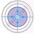 |
\[A\propto\frac{1}{r}\] | \[I\propto\frac{1}{r^2}\] |
| 2 | Cylindrical | Linear source / Slit | 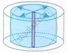 |
\[A\propto\frac{1}{\sqrt{r}}\] | \[I\propto\frac{1}{r}\] |
| 3 | Plane | Extended large source/ Point source at very large distinct | 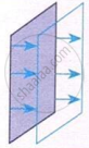 |
A = constant A ∝ r° | I = constant I ∝ r° |
- Light consists of energy-carrying photons guided by the rules of electromagnetic (EM) waves.
- Commonly observed phenomena of light are broadly classified into three categories: Ray optics, Wave optics, and Particle nature of light.
- Light thus exhibits a dual nature — it behaves both as a wave (wave optics) and as a particle (photon/particle nature), depending on the phenomenon observed.
- Every point on a wavefront acts as a secondary source (point source) that emits new spherical wavelets in all directions with the same speed as the original wave.
- The new (forward) wavefront at any later time is the common tangential envelope (tangent surface) to all these secondary wavelets.
- The wavefront in a medium is always perpendicular to the direction of wave propagation.
- Secondary wavelets travel only in the forward direction — backward wavelets are ignored (zero amplitude in backward direction).
Memory: Every point → new source → envelope = new wavefront.
| Parameter | Spherical Wavefront | Plane Wavefront | Cylindrical Wavefront |
|---|---|---|---|
| Obtained by | Point source at finite distance | Point source at infinity / large distance | Extended/linear source (slit) |
| Example | Tip of candle flame | Sunlight | Tube light |
| Wave normal | Along radius (diverging) | Parallel to each other | Along the radius |
| Amplitude (A) vs distance (r) |
A ∝ \[\frac {1}{r}\] |
A = constant | A ∝ \[\frac {1}{\sqrt r}\] |
| Intensity (I) vs distance (r) | I ∝ \[\frac {1}{r^2}\] | I = constant | I ∝ \[\frac {1}{r}\] |
- Diffraction = bending and spreading of light waves around obstacles or through narrow openings, producing interference patterns.
- It is due to interference of secondary wavelets from the exposed portion of the wavefront from the slit.
- Key difference from interference: in diffraction, bright fringes have same intensity but bands are of decreasing intensity.
Single Slit Diffraction:
Let a = width of slit, θ = angle of diffraction.
Condition for Minimum (Dark) Intensity:
Condition for Maximum (Secondary Bright) Intensity:
\[a\sin\theta=(2n+1)\frac{\lambda}{2},\quad n=1,2,3...\]
Width of Central Maximum:
For first minima: \[a\cdot\frac{y}{D}=\lambda\Rightarrow y=\frac{\lambda D}{a}\]
\[W=2y=\frac{2\lambda D}{a}\]
Angular width of central maximum:
Linear width of n-th secondary maximum:
Concepts [21]
- Concept of Wave Optics
- Nature of Light
- Light as a Wave
- Huygens Principle
- Reflection of Light at a Plane Surface
- Refraction of Light at a Plane Boundary Between Two Media
- Polarisation of Light
- Interference
- Coherent and Incoherent Sources and Sustained Interference of Light
- Young's Double Slit Experiment and Expression for Fringe Width
- Conditions for Producing Steady Interference Pattern
- Methods for Obtaining Coherent Sources
- Optical Path
- Diffraction of Light
- Fresnel and Fraunhofer Diffraction
- Experimental Set up for Fraunhofer Diffraction
- Fraunhofer Diffraction Due to a Single Slit
- Young’s Double Slit vs Single Slit
- Resolving Power
- Rayleigh’s Criterion
- Resolving Power of a Microscope and Telescope
