Advertisements
Advertisements
Question
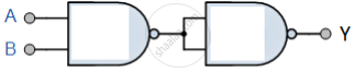
You are given circuit as shown in the figure, which consists of NAND gate. Identify the logic operation carried out by the two. Write the truth table. Identify the gates equivalent to the tow circuits.

Advertisements
Solution

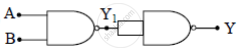
Y1 = Error! Objects cannot be created from editing field codes.
`"Y" = overline((bar"A.B").(bar"A.B")) = overline(bar"A.B").overline(bar"A.B") = ("A.B")+("A.B")`
= `"A"."B"`
The equivalent gate is AND Gate
Truth table
| A | B | Y1 | Y |
| 0 | 0 | 1 | 0 |
| 0 | 1 | 1 | 0 |
| 1 | 0 | 1 | 0 |
| 1 | 1 | 0 | 1 |
APPEARS IN
RELATED QUESTIONS
Write the truth table for the combination of the gates shown. Name the gates used.

Identify the logic gates marked 'P' and 'Q' in the given circuit. Write the truth table for the combination.

Identify the logic gate represented by the circuit as shown and write its truth table.

The output of an OR gate is connected to both the inputs of a NAND gate Draw the logic circuit of this combinaion of getes and write its truth table.
An AND gate can be prepared by repetitive use of
(a) NOT gate
(b) OR gate
(c) NAND gate
(d) NOR gate.
The outputs of two NOT gates are fed to a NOR gate. Draw the logic circuit of the combination of gates. Write its truth table. Identify the gate equivalent to this circuit.
The current obtained from a simple filterless rectifier is
The output of 2-input or gate is zero only when its
Identify the logic operation carried out by the given circuit:

The given figure shows the waveforms for two inputs A and B and that for the output Y of a logic circuit. The logic circuit is ______.
