Advertisements
Advertisements
Question
Obtain the expression for the applied emf and the effective resistance of the circuit when alternating emf is applied to an LR circuit.
Answer in Brief
Advertisements
Solution
- Consider an alternating e.m.f. applied to a series combination of the pure inductor of inductance L and resistor of resistance R.

- Let eR and eL be the r.m.s. the voltage across resistor and inductor respectively. As R and L are in series, the current at any instant is given as i = i0 sin ωt.
- Vector diagram,
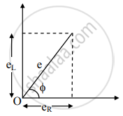
- From the above figure,
e2 = `"e"_"R"^2 + "e"_"L"^2`
∴ e = `sqrt("e"_"R"^2 + "e"_"L"^2) = sqrt(("iR")^2 + ("iX"_"L")^2) = "i"sqrt("R"^2 + "X"_"L"^2)`
∴ e = iZ
where Z = `sqrt("R"^2 + "X"_"L"^2)` is the impedance of the RL circuit. - a. Expression for applied emf in RL circuit,
e = e0sinωt = `sqrt("e"_"R"^2 + "e"_"L"^2)` = iZ
b. Expression for effective resistance in RL circuit, Z = `sqrt("R"^2 + "X"_"L"^2)`
shaalaa.com
Is there an error in this question or solution?
