Advertisements
Advertisements
Question
From the logic gate diagram given below:
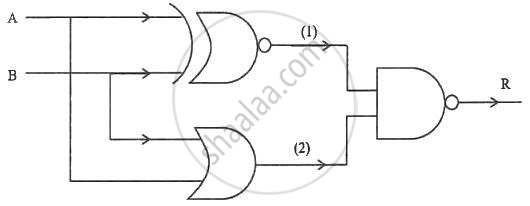
- Derive Boolean expression for (1), (2) and R. Reduce the derived expression. [4]
- Name the logic gate that represents the reduced expression. [1]
Long Answer
Advertisements
Solution
- The output of the first OR gate is (1) = A + B.
This output is then inverted by the NOT gate, giving (1)' = (A + B)'.
The expression for the second OR gate is (2) = A + B.
The final AND gate receives inputs (1)' and (2).
Thus, the resulting expression is:
R = A + B • (A + B)
Applying the absorption principle (where X•X' = 0), the value of R becomes 0, indicating that the output is always zero, regardless of the inputs. - The circuit is a grounded logic gate (always LOW) as the simplified equation shows a constant 0 function.
shaalaa.com
Is there an error in this question or solution?
2024-2025 (March) Official Board
