Advertisements
Advertisements
Question
Describe a set up for plotting the magnetic lines of force in: (i) A straight wire, (ii) A circular coil and (iii) A straight solenoid.
Advertisements
Solution
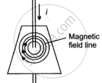
(i) A set-up for plotting the magnetic lines of force in a straight wire is shown in the diagram. A smooth cardboard with a hole at the centre is placed horizontally and a wire passes vertically through the hole. Some iron filings are sprinkled on the card-board and an electric current is passed through the wire. On slightly tapping the card-board the iron filing arrange themselves in concentric circle around the wire, as shown in the diagram. The direction of magnetic lines of force is clockwise since the current in the straight wire is flowing downwards. If the current flow is upwards then the direction of lines of force is anti-clockwise. See the following diagram:

(ii) Arrangement of the apparatus is the same, as in (a), only the wire is in the form of a circular coil and is passing through two holes, A and B in the cardboard. On passing the current through the circular coil, iron filings sprinkled on the horizontal surface of the smooth cardboard make a pattern of the lines of force, as shown in the diagram.
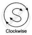

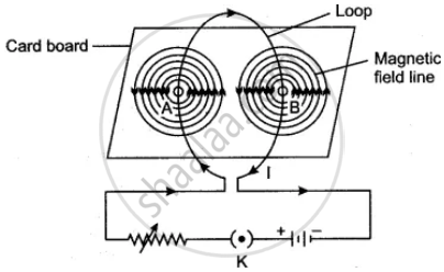
One face of the coil has north polarity while the other face shows south polarity, in accordance with the following rule: Looking at one face of the coil, if the direction of the current is anti-clockwise, that face has north polarity and the opposite face has south polarity.
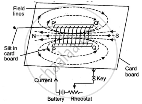
(iii) The accompanying diagram illustrates the pattern of magnetic lines of force in a straight solenoid. As shown in the diagram, the solenoid behaves like a cylindrical magnet having North and South poles at free ends. If the current flows in the reverse direction, the polarity at the free ends is also reversed.
RELATED QUESTIONS
Draw a diagram showing the directions of three magnetic field lines due to a straight wire carrying current. Also show the direction of current in the wire.
How is the magnetic field due to a straight current carrying wire affected if current in wire is decreased?
How is the magnetic field due to a straight current carrying wire affected if current in wire is reversed?
What is the nature of the lines of force of the magnetic field due to a straight current carrying wire?
In the diagram XY is a straight conductor carrying current in the direction marked by the arrow. The conductor is held vertical by passing it through a horizontal cardboard sheet.
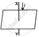
Draw three magnetic lines of force on the board and mark the direction of magnetic field in your diagram. State two factors on which magnitude of magnetic field at a point, depends.
Which of the following statement is not correct about the magnetic field?
A magnetic compass needle is placed in the plane of paper near point A as shown in Figure. In which plane should a straight current carrying conductor be placed so that it passes through A and there is no change in the deflection of the compass? Under what condition is the deflection maximum and why?

These consist of two statements – Assertion (A) and Reason (R). Answer these questions selecting the appropriate option given below:
Assertion: On freely suspending a current – carrying solenoid, it comes to rest in Geographical N-S direction.
Reason: One end of current carrying straight solenoid behaves as a North pole and the other end as a South pole, just like a bar magnet.
Two LED bulbs of 12W and 6W are connected in series. If the current through 12W bulb is 0.06A the current through 6W bulb will be ______.
- Assertion: A compass needle is placed near a current-carrying wire. The deflection of the compass needle decreases when the magnitude of the current in the wire is increased.
- Reason: The strength of a magnetic field at a point near the conductor increases by increasing the current.
