Advertisements
Advertisements
Question
A 220 V A.C. supply is connected between points A and B (figure). What will be the potential difference V across the capacitor?

Options
220 V
110 V
O V
`220 sqrt(2)` V
Advertisements
Solution
`220 sqrt(2)` V
Explanation:
Half wave rectifier: When the P-N junction diode rectifies half of the ac wave, it is called a half-wave rectifier.

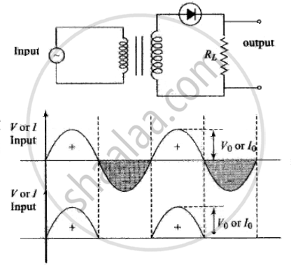
(i) During positive half cycle,
Diode → forward biased
Output signal → obtained
(ii) During the negative half cycle,
Diode → reverse biased
Output signal → not obtained
(iii) Output voltage is obtained across the load resistance RL. It is not constant but pulsating (mixture of ac and dc) in nature.
(iv) Average output in one cycle
`I_(dc) = I_0/pi` and `V_(dc) = V_0/pi, I_0 = V_0/(r_f + R_L)` .....(`r_f` = forward based resistance)
(v) r.m.s. output: `I_(rms) = I_0/2, V_(rms) = V_0/2`
As p-n junction diode will conduct during the positive half cycle only, during negative half cycle diode is reverse biased. During this diode will not give any output. So, the potential difference across capacitor C = peak voltage of the given AC voltage = `V_0 = V_(rms) sqrt(2) = 220 sqrt(2) V`
APPEARS IN
RELATED QUESTIONS
Draw the circuit diagram of a full wave rectifier. Explain its working showing its input and output waveforms.
Draw the circuit diagram of a half wave rectifier and explain its working.
In half-wave rectification, what is the output frequency if the input frequency is 50 Hz. What is the output frequency of a full-wave rectifier for the same input frequency.
When the diode shows saturated current, dynamic place resistance is _____________ .
The ability of a junction diode to ______ an alternating voltage is based on the fact that it allows current to pass only when it is forward biased.
Draw the circuit diagram of a full wave rectifier.
Explain with a proper diagram how an ac signal can be converted into dc (pulsating) signal with output frequency as double than the input frequency using pn junction diode. Give its input and output waveforms.
The device which uses centre-tapped secondary of the transformer is
The output of the given circuit in figure is given below.

To reduce the ripples in a rectifier circuit with capacitor filter ______.
- RL should be increased.
- input frequency should be decreased.
- input frequency should be increased.
- capacitors with high capacitance should be used.
Draw the output waveform across the resistor (Figure).
With the help of a circuit diagram, explain briefly how a p-n junction diode works as a half-wave rectifier.
Give two differences between a half-wave rectifier and a full-wave rectifier.
Name the device which utilizes the unilateral action of a pn diode to convert ac into dc.
Draw a labelled circuit diagram of a full wave rectifier. Show graphically how the output voltage varies with time.
