Advertisements
Advertisements
प्रश्न
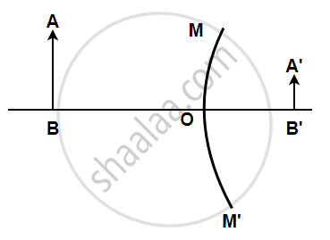
AB is the object, A1B1 is its image. MM' is the position of the mirror. Complete the ray diagram and find the position of the center of curvature and focus of the mirror. Also, measure the focal length.
Advertisements
उत्तर
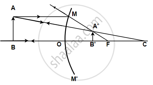
A light ray coming from a point on object AB is reflected from the surface of the mirror. When this ray is produced backwards, it passes through the principal focus and the ray which traces its incident path after reflection, when produced backwards, passes through the centre of curvature. These two reflected rays coincide at a point where the image is formed. The image, A'B' is virtual, erect, and diminished in size The focal length was found to be 24 mm.
APPEARS IN
संबंधित प्रश्न
A virtual image larger than the object can be produced by a ______.
Define Radius of curvature of the spherical mirror
A lens forms a real image 3 cm high of an object 1 cm high. If the separation of object and image is 15 cm, find the focal length of the lens.
An optical device has been given to a student and he determines its focal length by focusing the image of the sun on a screen placed 24 cm from the device on the same side as the sun. Select the correct statement about the device.
(A) Convex mirror of focal length 12 cm
(B) Convex lens of focal length 24 cm
(C) Concave mirror of focal length 24 cm
(D) Convex lens of focal length 12 cm
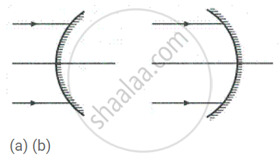
Name the mirrors shown in Figure (a) and (b).
In torches, search lights and headlights of vehicles the bulb is placed ______.
Size of image of an object by a mirror having a focal length of 20 cm is observed to be reduced to 1/3rd of its size. At what distance the object has been placed from the mirror? What is the nature of the image and the mirror?
What is the difference between virtual images of an object formed by a concave mirror and a convex mirror?
