Advertisements
Advertisements
प्रश्न
A 2 µF capacitor, 100 Ω resistor and 8 H inductor are connected in series with an AC source.
(i) What should be the frequency of the source such that current drawn in the circuit is maximum? What is this frequency called?
(ii) If the peak value of e.m.f. of the source is 200 V, find the maximum current.
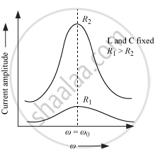
(iii) Draw a graph showing variation of amplitude of circuit current with changing frequency of applied voltage in a series LRC circuit for two different values of resistance R1 and R2 (R1 > R2).
(iv) Define the term 'Sharpness of Resonance'. Under what condition, does a circuit become more selective?
Advertisements
उत्तर
(i) To draw maximum current from a series LCR circuit, the circuit must be at resonance. For resonance, we know at particular frequency
\[X_L = X_C\] The frequency of the source will be
\[\nu = \frac{1}{2\pi\sqrt{LC}}\]
\[ = \frac{1}{2 \times 3 . 14 \times \sqrt{8 \times 2 \times {10}^{- 6}}}\]
\[ = 39 . 80 Hz\]
This frequency is known as the series resonance frequency.
(ii) The maximum current will be given by
\[I_0 = \frac{E_0}{R}\]
\[ = \frac{200}{100}\]
\[ = 2 A\]
(iii)
(iv)
Sharpness of Resonance : It is defined as the ratio of the voltage developed across the inductance (L) or capacitance (C) at resonance to the voltage developed across the resistance (R).
\[Q = \frac{1}{R}\sqrt{\frac{L}{C}}\]
It may also be defined as the ratio of resonance angular frequency to bandwidth of the circuit.
\[Q = \frac{\omega_r}{2 ∆ \omega}\]
Circuit become more selective if the resonance is more sharp, maximum current is more, the circuit is close to resonance for smaller range of (2
\[∆ \omega\] of frequencies. Thus, the tuning of the circuit will be good.
APPEARS IN
संबंधित प्रश्न
When an AC source is connected to a capacitor, there is a steady-state current in the circuit. Does it mean that the charges jump from one plate to the other to complete the circuit?
Is energy produced when a transformer steps up the voltage?
A transformer is designed to convert an AC voltage of 220 V to an AC voltage of 12 V. If the input terminals are connected to a DC voltage of 220 V, the transformer usually burns. Explain.
A bulb rated 60 W at 220 V is connected across a household supply of alternating voltage of 220 V. Calculate the maximum instantaneous current through the filament.
Compare resistance and reactance.
Average power supplied to a capacitor over one complete cycle is ______.
In the LCR circuit shown in figure, the ac driving voltage is v = vm sin ωt.
- Write down the equation of motion for q (t).
- At t = t0, the voltage source stops and R is short circuited. Now write down how much energy is stored in each of L and C.
- Describe subsequent motion of charges.

The resistance of a coil for d.c. is 5 Ω. In a.c., the resistance will ______.
