Advertisements
Advertisements
प्रश्न
A 2 µF capacitor, 100 Ω resistor and 8 H inductor are connected in series with an AC source.
(i) What should be the frequency of the source such that current drawn in the circuit is maximum? What is this frequency called?
(ii) If the peak value of e.m.f. of the source is 200 V, find the maximum current.
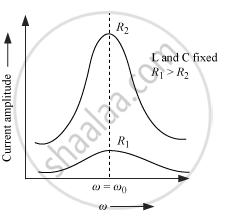
(iii) Draw a graph showing variation of amplitude of circuit current with changing frequency of applied voltage in a series LRC circuit for two different values of resistance R1 and R2 (R1 > R2).
(iv) Define the term 'Sharpness of Resonance'. Under what condition, does a circuit become more selective?
Advertisements
उत्तर
(i) To draw maximum current from a series LCR circuit, the circuit must be at resonance. For resonance, we know at particular frequency
\[X_L = X_C\] The frequency of the source will be
\[\nu = \frac{1}{2\pi\sqrt{LC}}\]
\[ = \frac{1}{2 \times 3 . 14 \times \sqrt{8 \times 2 \times {10}^{- 6}}}\]
\[ = 39 . 80 Hz\]
This frequency is known as the series resonance frequency.
(ii) The maximum current will be given by
\[I_0 = \frac{E_0}{R}\]
\[ = \frac{200}{100}\]
\[ = 2 A\]
(iii)
(iv)
Sharpness of Resonance : It is defined as the ratio of the voltage developed across the inductance (L) or capacitance (C) at resonance to the voltage developed across the resistance (R).
\[Q = \frac{1}{R}\sqrt{\frac{L}{C}}\]
It may also be defined as the ratio of resonance angular frequency to bandwidth of the circuit.
\[Q = \frac{\omega_r}{2 ∆ \omega}\]
Circuit become more selective if the resonance is more sharp, maximum current is more, the circuit is close to resonance for smaller range of (2
\[∆ \omega\] of frequencies. Thus, the tuning of the circuit will be good.
APPEARS IN
संबंधित प्रश्न
When an AC source is connected to a capacitor, there is a steady-state current in the circuit. Does it mean that the charges jump from one plate to the other to complete the circuit?
A device Y is connected across an AC source of emf e = e0 sin ωt. The current through Y is given as i = i0 sin (ωt + π/2).
- Identify the device Y and write the expression for its reactance.
- Draw graphs showing a variation of emf and current with time over one cycle of AC for Y.
- How does the reactance of the device Y vary with the frequency of the AC? Show graphically.
- Draw the phasor diagram for device Y.
When an ac voltage of 220 V is applied to the capacitor C, then ______.
A capacitor has capacitance C and reactance X, if capacitance and frequency become double, then reactance will be ______.
A resistor of 50 Ω, a capacitor of `(25/pi)` µF and an inductor of `(4/pi)` H are connected in series across an ac source whose voltage (in volts) is given by V = 70 sin (100 πt). Calculate:
- the net reactance of the circuit
- the impedance of the circuit
- the effective value of current in the circuit.
What is the charge on the capacitor at time \[t\]?
What happens when a DC source is connected to a capacitor?
How does a lamp in series with a capacitor behave when connected to an AC source?
What is the peak current when the rms current is \[1.04\,\mathrm{A}\]?
How does inserting an iron rod into the inductor affect its inductive reactance?
