Definitions [34]
It is defined as the magnitude of the drift velocity of the charge carriers per unit electric field.
\[\mu=\frac{v_d}{E}=\frac{e\tau}{m}\]
The S.I. unit of mobility is \[\mathrm{m^{2}s^{-1}~V^{-1}}\] or \[\mathrm{ms^{-1}N^{-1}C}\]
Electric current is defined as the amount of electric charges flowing through any cross-section of a conductor per unit time.
\[I=\frac{\text{Total charge flowing (Q)}}{\text{Time taken (t)}}\]
\[I=\frac{Q}{t}\]
The S.I. unit of current is ampere (A)
Electric current through a conductor is said to be one ampere if charge of one coulomb flows through any cross-section of the conductor in one second.
\[1\mathrm{~ampere~(A)}=\frac{1\mathrm{~coulomb~(C)}}{1\mathrm{~second~(s)}}=1\mathrm{~C~s}^{-1}\]
It is defined as the velocity with which the free electrons are drifted towards the positive terminal under the effect of the applied electric field.
- The drift velocity of electrons is given by \[v_d=\frac{eE\tau}{m}\]
At constant temperature and other physical conditions, the current flowing through a conductor is directly proportional to the potential difference across its ends.
Define the following:
Coulomb
One coulomb is the amount of electric charge transferred by a current of one ampere in one second.
Define Current density.
Current density is a vector quantity, often known as an area vector or cross-sectional area vector, whose value is equal to the electric current flowing per unit area.
J = `"I"/"A"`
S.I unit is A/m2.
One ohm is the resistance of a component when the potential difference of one volt applied across the component drives a current of one ampere through it.
Define temperature coefficient of resistance.
The temperature coefficient is defined as the ratio of the increase in resistivity per degree rise in temperature to its resistivity at T0.
The conductors which do not obey Ohm's law are called non-ohmic resistors (or non-linear resistances).
i.e., Current depends on voltage, but it does not vary linearly.
The conductors which obey Ohm's law are called ohmic resistors (or linear resistances).
i.e., Voltage and current vary linearly in ohmic conductors/materials.
The electrical energy consumed in a circuit is defined as the total work done in maintaining the current in the electric circuit for a given time.
Electrical Energy = \[VIt=I^2Rt=\frac{V^2t}{R}\]
S.I. unit of electric energy is joule (1 kWh = \[3.6\times10^6\mathrm{~J}\])
In an electrical circuit, electric power is defined as the rate at which electrical energy is supplied by the source.
Define Electric power.
Electric power (P) is the rate at which electrical energy is transferred or consumed in an electrical circuit.
What does the unit kilowatt hour measure? Define it.
The unit kilowatt-hour measures electrical energy. 1 kWh is the electrical energy consumed by an electric appliance of power 1 kW when it is used for 1 hour.
Electrical Resistivity (ρ) is defined as the resistance offered by a conductor of unit length and unit cross-sectional area at a given temperature. It is a characteristic property of the material, independent of its dimensions.
Electrical conductivity, or conductivity of a substance, is equal to the inverse of its resistivity.
\[\sigma=\frac{1}{\rho}\]
- SI unit: S m⁻¹
- Dimensions: [M⁻¹ L⁻³ T³ A²]
Conductance of a substance is equal to the inverse of its resistance.
\[G=\frac{1}{R}\]
- S.I. unit: ohm−1 or mho or siemens (S).
- Dimensions: [M⁻¹ L⁻² T³ A²]
The amount of electric current flowing per unit cross-sectional area of a conductor, measured at a point perpendicular to the direction of current flow.
Electric resistance is the property of a conductor by virtue of which it opposes the flow of electric current through it.
R = \[\frac {V}{I}\]
Define the following:
Variable resistor
A variable resistor has a resistance that can be varied. It is used to vary the amount of current flowing in a circuit.
Conductance is the reciprocal of resistance — a measure of how easily current flows through a conductor.
G = \[\frac {1}{R}\]
Define the term resistance.
Resistance is the obstacle that the wire presents to the current flow.
Define the following:
Fixed resistor
A fixed resistor has a resistance of a fixed value. Common types of fixed resistors include carbon film resistors and wire-wound resistors.
Resistivity is a material-dependent property that measures how strongly a material opposes current flow, independent of its shape or size.
ρ = \[\frac {RA}{l}\]
The temperature coefficient of resistivity, denoted by α, measures the fractional change in resistivity per degree change in temperature in the linear range.
- Unit: per degree Celsius or per kelvin.
- For metals, α > 0.
- For semiconductors, α < 0.
Resistivity, denoted by ρ, is the intrinsic property of a material that determines how much it resists current flow.
The resistance offered by the electrolyte of the cell when an electric current flows through it is known as internal resistance.
When current is drawn through a cell or current is supplied to it, then the potential difference across its terminals is called the terminal potential difference.
\[V=E-Ir\]
The emf of a cell is defined as the work done in carrying a unit positive charge through the complete circuit, including the charge flow inside the cell.
Unit: J/C (or) volt
Electromotive Force (emf) is the work done by a cell (or any energy source) in driving a unit positive charge around the complete circuit, including through the cell itself.
An arrangement of four resistors used to measure the resistance of one of them in terms of the other three, invented by Samuel Hunter Christie in 1833 and made famous by Sir Charles Wheatstone, is called a Wheatstone bridge.
The condition of the Wheatstone bridge under which the galvanometer shows zero (null) deflection, i.e., Ig = 0, is called the balance condition of the bridge.
A metre bridge (slide-wire bridge) is a practical laboratory device based on the Wheatstone bridge principle, used to measure an unknown electrical resistance by achieving a null-point (balance) condition on a one-metre-long uniform resistance wire.
Formulae [7]
V ∝ I
V = IR
Other useful forms: I = \[\frac {V}{R}\] or R = \[\frac {V}{I}\]
Electric Power P = \[\frac {W}{t}\] = VI = \[\frac {V^2}{R}\] = I2R
For a conductor of uniform cross-sectional area A carrying current I perpendicular to the surface:
j = \[\frac {I}{A}\]
SI Unit: ampere per square metre (A/m2)
Dimensional Formula: [A L−2]
RT = R0(1 + αΔT)
where ΔT = T − T0.
ρT = ρ0[1 + α(T − T0)]
Here:
- ρT = resistivity at temperature T.
- ρ0 = resistivity at reference temperature T0.
- α = temperature coefficient of resistivity.
ε = \[\frac {dW}{dq}\]
SI Unit: volt (V), where 1 V = 1 J C−1
Dimensional Formula: [ML2T−3A−1]
Balance condition (when Ig = 0):
- AC → battery arm
- BD → galvanometer arm
- R4 → unknown resistance measured in terms of the other three.
Theorems and Laws [9]
Statement: Ohm’s Law
"The electric current flowing through a conductor is directly proportional to the potential difference across its ends, provided the temperature and other physical conditions of the conductor remain constant."
Mathematically,
I ∝ V or V = I R
where:
- V = Potential difference (in volts)
- I = Current (in amperes)
- R = Resistance of the conductor (in ohms, Ω)
Explanation:
When two conductors at different electric potentials are joined by a metallic wire, electrons flow from the conductor at a lower potential (excess electrons) to the one at a higher potential (deficit of electrons). This movement of electrons results in an electric current.
- The current continues to flow until both conductors reach the same potential.
- For continuous current flow, a constant potential difference must be maintained across the ends of the conductor (e.g., using a battery or power supply).
Derivation / Mathematical Proof:
From Ohm’s Law:
I ∝ V ⇒ \[\frac {V}{I}\] = constant
This constant is defined as the resistance (R) of the conductor. Therefore,
V = I R ---(1)
This is the mathematical form of Ohm’s Law.
Special Case:
If the current I = 1 A, then:
V = R
This implies that the resistance of a conductor is numerically equal to the potential difference across it when 1 ampere of current flows through it.
Conclusion:
Ohm's Law provides a fundamental relationship between voltage, current, and resistance in an electric circuit. It is widely used in the design and analysis of electrical and electronic systems.
According to Ohm’s law, the current flowing in a conductor is directly proportional to the potential difference across its ends, provided the physical conditions and temperature of the conductor remain constant.
No, it is not always true. E.g., Diode valve, junction diode, etc., do not obey Ohm’s law.
State Ohm’s law.
According to Ohm’s law, at a constant temperature, the steady current ‘I’ flowing through a conductor is directly proportional to the potential difference ‘V’ between the two ends of the conductor.
I ∝ V
V = IR
At any junction, the sum of currents entering = the sum of currents leaving.
Example: I1 + I3 = I2 + I4. Based on conservation of charge.
Statement
At any junction in an electric circuit, the sum of currents entering the junction is equal to the sum of currents leaving the junction.
Derivation
When the current in a circuit is steady, charge does not accumulate at any junction. Therefore, the amount of charge entering the junction per second must be equal to the amount of charge leaving the junction per second.
If currents I1 and I2 enter a junction and currents I3 and I4 leave it, then
or
Hence,
Conclusion
Kirchhoff's First Law is a direct consequence of the conservation of charge.
Statement
In any closed loop of an electric circuit, the algebraic sum of all changes in potential is zero.
Derivation
Consider a charge moving around a closed loop. After completing one full loop, the charge returns to its starting point. Since electric potential depends only on position, the net change in potential over a complete loop must be zero.
Therefore, in a closed loop,
If a loop contains cells and resistors, then the total emf supplied by the sources is equal to the total potential drop across the resistors. Thus,
Conclusion
Kirchhoff's Second Law is a direct consequence of the conservation of energy.
The algebraic sum of potential differences in a closed loop is zero.
Based on conservation of energy.
Obtain the balancing condition for the Wheatstone bridge arrangements as shown in Figure 4 below:
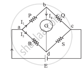
Let `I_3` and `I_4` be the currents in resistors Q and S respectively . Let `I_g` be the current through galvanometer. For balanced condition,
`I_g = 0`
Applying junction law at ‘b’ we get
`I_1 = I_3 + I_g`
`because I_g = 0 , I_1 = I_3` ....(i)
Applying junction law at ‘d’, we get
`I_2 + I_g = I_4`
`because I_g = 0 , I_2 = I_4` ....(ii)
Applying loop law in the loop abda, we get
`-I_1·P - I_g·Q + -I_2·R = 0`
⇒ `-I_1P + I_2R = 0` (`because I_g = 0`)
⇒ `I_1P = I_2R`
⇒ `P/R = I_2/I_1` ....(iii)
Applying loop law in the loop bcdb, we get
`-I_3·Q + I_4·S + I_g·6 = 0`
⇒ `-I_3·Q + I_4·S + 0 = 0 (because I_g =0)`
⇒ `-I_3Q = I_4S`
⇒ `Q/S = I_4/I_3`
⇒ `Q/S = I_2/I_1` ...(iv) [using eq.(i) and (ii)]
From eq. (iii) and (iv), `P/ R = Q/s`
⇒ `P/Q = R/S`
This is the balanced condition.
The metre bridge works on the Wheatstone bridge principle: a bridge circuit is said to be balanced when no current flows through the galvanometer, i.e., points B and D are at the same potential.
Key Points
- Electrical power represents the rate at which electrical energy is supplied by the source in an electric circuit.
- The S.I. unit of electrical power is a watt (W), and larger units such as kilowatt, megawatt, and gigawatt are used for measuring higher power.
Resistivity and Temperature:
\[\rho_T=\rho_0[1+\alpha(T-T_0)]\]
Resistance and Temperature:
\[R_T=R_0(1+\alpha\Delta T)\]
Temperature Coefficient (α):
- Unit: °C⁻¹ (or K⁻¹)
- Metals: α > 0→ resistivity increases with temperature
Semiconductors & insulators:
α < 0 → resistivity decreases with temperature
- In series, resistors are connected one after another (in a single path).
- Current is the same through all resistors.
Equivalent resistance:
Req = R₁ + R₂ + R₃ + ...
For n identical resistors:
Req = nR
Voltage relation:
V = V₁ + V₂ + V₃
Voltage divider rule:
V₁ : V₂ : V₃ = R₁ : R₂ : R₃
Req > Rmax
- In parallel, resistors are connected across the same two points (multiple paths).
- Voltage is the same across all resistors.
Equivalent resistance:
\[\frac{1}{R_{eq}}=\frac{1}{R_1}+\frac{1}{R_2}+\frac{1}{R_3}+\cdots\]
For n identical resistors:
Req = R/n
Current relation:
I = I₁ + I₂ + I₃
Current divider rule:
I₁ : I₂ : I₃ = \[\frac{1}{R_{1}}:\frac{1}{R_{2}}:\frac{1}{R_{3}}\]
Req < Rmin
- Cells are connected from the positive terminal to the negative terminal.
- Total emf is the sum of individual emfs:
Enet = E₁ + E₂ + E₃ + ... - Total internal resistance:
rnet = r₁ + r₂ + r₃ + ... - For n identical cells:
Enet = nE
rnet = nr - Current in the circuit:
\[I=\frac{E_{\mathrm{net}}}{r_{\mathrm{net}}+R}\] - For identical cells:
\[I=\frac{nE}{nr+R}\]
- All positive terminals are connected together, and all negative terminals are connected together.
- Total emf remains the same:
Enet = E - Internal resistance reduces:
\[r_{net}=\frac{r}{n}\] - Current in the circuit:
I = E / (R + rnet) - For identical cells:
\[I=\frac{E}{R+r_{net}}=\frac{E}{R+\frac{r}{n}}=\frac{nE}{nR+r}\]
- Kirchhoff's laws are used for complex circuits.
- Kirchhoff's First Law: Total current entering a junction = total current leaving a junction.
- Kirchhoff's Second Law: Total potential rise in a closed loop = total potential drop in the loop.
- KCL is based on conservation of charge.
- KVL is based on conservation of energy.
- Mathematical forms are ∑I = 0 and ∑V = 0.
- The correct sign convention is essential in numericals.
Concepts [19]
- Electric Current and Its Related Concepts
- Ohm's Law
- Ohmic and Non-ohmic Resistors
- Forms of Energy > Electrical Energy
- Electrical Power
- Specific Resistance or Electrical Resistivity
- Conductivity and Conductance
- Current Density
- Electric Resistance
- Temperature Dependence of Resistivity
- Resistors in Series
- Resistors in Parallel
- Cells, EMF, and Internal Resistance
- Electromotive Force of a Cell
- Cells in Series
- Cells in Parallel
- Kirchhoff’s Laws
- Wheatstone Bridge
- Metre Bridge: Slide-Wire Bridge
