Advertisements
Advertisements
प्रश्न
With the help of a neat diagram, explain the working of the npn transistor?
Advertisements
उत्तर
Working of n-p-n transistor:
- The majority of charge carriers in the emitter of the n-p-n transistor are electrons.
- A typical biasing of a transistor is shown in figure (a). In this, the emitter-base junction is forward biased while the collector-base junction is reverse biased.

Figure (a) - At the instant when the EB junction is forward biased, electrons in the emitter region have not entered the base region as shown in figure (b).

Figure (b) - When the biasing voltage VBE is greater than the barrier potential (0.6 – 0.7 V for Si transistors), many electrons enter the base region and form the emitter current IE as shown in figure (c).
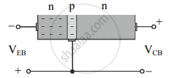
Figure (c) - These electrons can either flow through the base circuit and constitute the base current (IB), or they can also flow through the collector circuit and contribute towards the collector current (IC).
- The base is thin and lightly doped, the base current is only 5% of IE.
- Electrons injected from the emitter into the base diffuse into the collector-base depletion region due to the thin base region. When the electrons enter the collector-base depletion region, they are pushed into the collector region by the electric field at the collector-base depletion region. The collector current (IC) flows through the external circuit as shown in figure (d). The collector's current IC is about 95% of IE.

Figure (d)
From the figure, we can conclude that IE = IB + IC Since the base current IB is very small we can write IC ≈ IE.
APPEARS IN
संबंधित प्रश्न
In a BJT, the largest current flow occurs ______.
Why are the emitter, the base, and the collector of a BJT doped differently?
The common-base DC current gain of a transistor is 0.967. If the emitter current is 10mA. What is the value of base current?
Draw the circuit symbol of the PNP transistor.
For a transistor IC = 15 mA, IB = 0.5 mA. What is the current amplification factor?
Explain the need for a feedback circuit in a transistor oscillator.
What is rectification?
The condition to convert an amplified signal into an oscillating signal is ______
A transistor having α = 0.8 is connected in common emitter configuration. When the base current changes by 6 mA, then the change in collector current is ______.
In an npn transistor, the base current is 100 µA and the collector current is 10 mA. The emitter current is ______.
Which of the following regions of a transistors are, respectively, heavily dopped and lightly dopped?
In a common emitter amplifier circuit using an n-p-n transistor, the phase difference between the input and the output voltages will be: ____________.
In case of npn transistors, the collector current is always less than the emitter current because ______.
In an npn transistor circuit, the collector current is 10 mA. If 90% of the electrons emitted reach the collector, the emitter current (IE) and base current (IB) are given by ____________.
In a transistor, doping level in base is increased slightly, the collector current and base current respectively ______.
In transistor amplifier, base-emitter junction is forward biased and collector emitter junction is reverse biased. The current gain is ______.
In common emitter mode of transistor, the d.c. current gain is 20, the emitter current is 7 mA. The collector current is ______.
A transistor is connected in C - E mode. If collector current is 72 × 10-5 A and α = 0.96, then base current will be ______.
For an ideal diode, the current in the following arrangement is ______.

In the common-emitter configuration of a transistor, the current gain is more than 1 because [lb, le, and lc are base, emitter, and collector currents respectively] ______
The reverse bias in a junction diode is changed from 8V to 13V, then the value of the current changes from 40μA to 60μA. The resistance of junction diode will be ______.
Explain the working of the n-p-n transistor in a common base configuration.
Explain the output characteristics of common emitter configuration of n-p-n transistor.
Define α.
In a transistor (common emitter configuration) the ratio of power gain to voltage gain is (α and β are current ratios) ______.
