Advertisements
Advertisements
प्रश्न
Draw a schematic sketch of an ac generator describing its basic elements. State briefly its working principle. Show a plot of variation of
(i) Magnetic flux and
(ii) Alternating emf versus time generated by a loop of wire rotating in a magnetic field.
Advertisements
उत्तर
Principle − Based on the phenomenon of electromagnetic induction.
Construction:
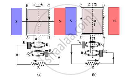
Main parts of an ac generator:
Armature − The rectangular coil ABCD
Filed Magnets − Two pole pieces of a strong electromagnet
Slip Rings − The ends of the coil ABCD are connected to two hollow metallic rings R1 and R2.
Brushes − B1 and B2 are two flexible metal plates or carbon rods. They are fixed and are kept in tight contact with R1 and R2, respectively.
Working − As the armature coil is rotated in the magnetic field, angle θ between the field and the normal to the coil changes continuously. Therefore, magnetic flux linked with the coil changes and an emf is induced in the coil. According to Fleming’s right hand rule, current is induced from A to B in AB and from C to D in CD. In the external circuit, current flows from B2 to B1.
To calculate the magnitude of emf induced:
Suppose A → Area of each turn of the coil
N → Number of turns in the coil
`vecB`→ Strength of the magnetic field
θ → Angle which normal to the coil makes with `vecB` at any instant t
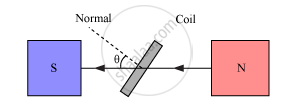
∴ Magnetic flux linked with the coil in this position is given by,
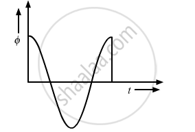
`phi=N(vecB.vecA)=NBAcostheta=NBAcos `
Where, ‘ω’ is angular velocity of the coil
Graph between magnetic flux and time, according to equation (i), is shown below:
As the coil rotates, angle θ changes. Therefore, magnetic flux Φ linked with the coil changes and an emf is induced in the coil. At this instant t, if e is the emf induced in the coil, then
`e=(dtheta)/dt=-d/dt(NABcos`
`=-NABd/dt(cos `
=-NAB(-sin ωt)ω
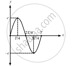
∴ e = NAB ω sin ωt
The graph between alternating emf versus time is shown below:
APPEARS IN
संबंधित प्रश्न
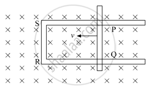
Figure shows a rectangular loop conducting PQRS in which the arm PQ is free to move. A uniform magnetic field acts in the direction perpendicular to the plane of the loop. Arm PQ is moved with a velocity v towards the arm Rs. Assuming that the arms QR, RS and SP have negligible resistances and the moving arm PQ has the resistance r, obtain the expression for (i) the current in the loop (ii) the force and (iii) the power required to move the arm PQ.
How does the mutual inductance of a pair of coils change when
(i) distance between the coils is increased and
(ii) number of turns in the coils is increased?
Whenever the magnetic flux linked with an electric circuit changes, an emf is induced in the circuit. This is called ______.
A circular coil of 1000 turns each with area 1 m2 is rotated about its vertical diameter at the rate of one revolution per second in a uniform horizontal magnetic field of 0.07T. The maximum voltage generation will be ______ V.
What is magnetic flux linked with any surface?
What is \[\theta\] in \[\Phi_B=BA\cos\theta\]?
How is a surface handled when calculating flux through a non-uniform magnetic field or a curved surface?
What is the flux when the magnetic field is at an angle \[\theta\] to the area vector?
What happens to magnetic flux when area \[A\] increases while magnetic field and orientation remain unchanged?
Why does the number of magnetic field lines entering a closed surface equal the number leaving it?
