Advertisements
Advertisements
प्रश्न
Sketch the static characteristics of a common emitter transistor and bring out the essential features of input and output characteristics.
Advertisements
उत्तर

Static characteristics of a NPN transistor in common emitter configuration
- The circuit to study the static characteristics of NPN transistor is given in figure
- Bias supply voltages VBB and VCC bias, base-emitter junction and collector-emitter junction.
- Junction potentials are VBE and YCE
- R1 and R2 are used to vary base and collector currents respectively.
1. Input Characteristics:
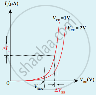
- Input Characteristics curve gives the relationship between IB and VBE at constant VCE
- For constant collector-emitter voltage VCE, Base emitter voltage VBE increases for corresponding Base current IB which is recorded and graph is ploted.
- The curve looks like forwarding characteristics.
- Beyond knee voltage base current increases with an increase in base-emitter voltage for silicon 0.7 V and for Germanium 0.3 V.
- Increase in VCE decreases IB. This shifts the curves outward.
- Input resistance Ri = `((Δ"V"_"BE")/(Δ"I"_"B"))_("V"_"CE")`
2. Output characteristics:

- The output characteristics give the relation between ∆IC with respect to ∆VCE at constant IB
- Initially base current IB is set to a particular value. Increasing collector-emitter voltage VCE corresponding collector current IC increases. A graph is plotted.
- Output resistance Ro = `((Δ"V"_"CE")/(Δ"I"_"C"))_"IB"`
The four important regions in the output characteristics are:
- Saturation region: When VCE increased above 0V, IC increases rapidly almost independent of IB called knee voltage Transistor operated above this knee voltage.
- Cut-off region: A small IC exists even after IB is reduced to zero. This current is due to the presence of minority carriers across the collector-base junction and the surface leakage current (ICEO). This region is called the cut-off region.
- Active region: In this region emitter-base junction is forward bias, collector-base junction is reverse bias. Transistors in this region can be used for voltage, current and power amplification.
- breakdown region: If VCE is increased beyond rated value, given Ic increases enormously leading to junction breakdown of the transistor. This avalanche breakdown can damage.
APPEARS IN
संबंधित प्रश्न
Why is the base of a transistor made thin and is lightly doped?
In a transistor amplifier, IC = 5.5 mA , IE = 5.6 mA. The current amplification factor β is ______
For a transistor IC = 15 mA, IB = 0.5 mA. What is the current amplification factor?
Draw the circuit symbol for NPN and PNP transistors. What is the difference in the Emitter, Base, and Collector regions of a transistor?
With the help of a neat circuit diagram, explain the transistor as an amplifier?
The principle based on which a solar cell operates is ____________.
For a common emitter configuration, if 'α' and 'β' have their usual meanings, the correct relationship between 'α' and 'β' is ______.
In transistor amplifier, base-emitter junction is forward biased and collector emitter junction is reverse biased. The current gain is ______.
The reverse bias in a junction diode is changed from 8V to 13V, then the value of the current changes from 40μA to 60μA. The resistance of junction diode will be ______.
Define peak value of alternating signal.
