Advertisements
Advertisements
प्रश्न
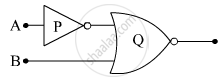
(i) Write the truth tables of the logic gates marked P and Q in the given circuit.
(ii) Write the truth table for the circuit.

Advertisements
उत्तर
(i) P and Q are the NOT and OR gates respectively. The truth table for them is drawn below:
| NOT | OR | |||
|---|---|---|---|---|
| Input | Output | Input 1 | Input 2 | Output |
| 1 | 0 | 1 | 1 | 1 |
| 0 | 1 | 0 | 0 | 0 |
| 1 | 0 | 1 | ||
| 0 | 1 | 1 | ||
(ii) The truth table for the whole network:
| Input -A | Input -B | Output |
|---|---|---|
| 1 | 1 | 1 |
| 0 | 0 | 1 |
| 1 | 0 | 0 |
| 0 | 1 | 1 |
संबंधित प्रश्न
The output of NOR gate is high, when _______.
Write the truth table for the combination of the gates shown. Name the gates used.

The logic gate which produces LOW output when one of the input is HIGH and produces
HIGH output only when all of its inputs are LOW is called _______.
(A) AND gate
(B) OR gate
(C) NOR gate
(D) NAND gate
Write the truth table for a NAND gate connected as given in the following figure.

Hence identify the exact logic operation carried out by this circuit
Write the truth table for circuit given in figure below consisting of NOR gates and identify the logic operation (OR, AND, NOT) which this circuit is performing.

(Hint: A = 0, B = 1 then A and B inputs of second NOR gate will be 0 and hence Y=1. Similarly work out the values of Y for other combinations of A and B. Compare with the truth table of OR, AND, NOT gates and find the correct one.)
The output of an OR gate is connected to both the inputs of a NAND gate Draw the logic circuit of this combinaion of getes and write its truth table.
Why are NOR gates considered as universal gates?
The outputs of two NOT gates are fed to a NOR gate. Draw the logic circuit of the combination of gates. Write its truth table. Identify the gate equivalent to this circuit.
A radar is sending out pules of 1 micro second duration at interval of 100 micro-second. The range of the radar is
Which logic gate is similar to a function of two series switches?
