Advertisements
Advertisements
प्रश्न
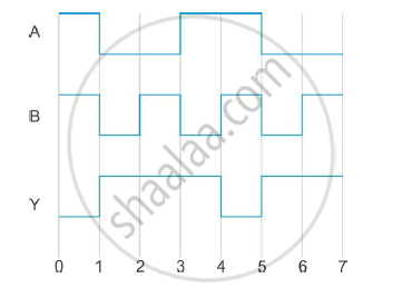
The following figure shows the input waveforms (A, B) and the output waveform (Y) of a gate. Identify the gate, write its truth table and draw its logic symbol.
Advertisements
उत्तर
The truth table for the gate can be obtained from the waveforms (from t = 1) as
| A | B |
`Y=bar(AB)` |
| 0 | 0 | 1 |
| 0 | 1 | 1 |
| 1 | 0 | 1 |
| 1 | 1 | 0 |
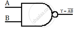
Therefore, from the truth table, we can say that the gate is a NAND gate. The logic symbol for the NAND gate is
shaalaa.com
या प्रश्नात किंवा उत्तरात काही त्रुटी आहे का?
