Advertisements
Advertisements
प्रश्न
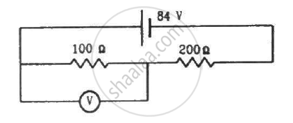
A voltmeter of resistance 400 Ω is used to measure the potential difference across the 100 Ω resistor in the circuit shown in the figure. (a) What will be the reading of the voltmeter? (b) What was the potential difference across 100 Ω before the voltmeter was connected?

Advertisements
उत्तर
(a) The effective resistance of the circuit,
\[R_{eff} = \frac{100 \times 400}{500} + 200 = 280 \Omega\]
The current through the circuit,
\[i = \frac{84}{280} = 0 . 3 A\]
Since 100 Ω resistor and 400 Ω resistor are connected in parallel, the potential difference will be same across their ends. Let the current through 100 Ω resistor be i1 ; then, the current through 400 Ω resistor will be i - i1.
\[100 i_1 = 400\left( i - i_1 \right)\]
\[ \Rightarrow 500 i_1 = 400i\]
\[ \Rightarrow i_i = \frac{4}{5}i = 0 . 24 A\]
The reading of the voltmeter = 100 × 0.24 = 24 V
(b) Before the voltmeter is connected, the two resistors 100 Ω resistor and 200 Ω resistor are in series.
The effective resistance of the circuit,
\[R_{eff} = \left( 200 + 100 \right)\]
\[ = 300 \Omega\]
The current through the circuit,
\[i = \frac{84}{300} = 0 . 28 A\]
∴ Voltage across the 100 Ω resistor = (0.28 × 100) = 28 V
APPEARS IN
संबंधित प्रश्न
When 5 V potential difference is applied across a wire of length 0.1 m, the drift speed of electrons is 2.5 x 10⁻⁴ m/s. If the electron density in the wire is 8 x 1028 m-3, calculate the resistivity of the material of the wire.
In a series LCR circuit, what is the phase difference between VL and VC where VL is the potential difference across the inductor and V c is the potential difference across the capacitor?
Describe the working principle of a solar cell. Mention three basic processes involved in the generation of emf.
Why are Si and GaAs preferred materials for solar cells?
Why is potentiometer preferred over a voltmeter for comparison of emf. of cells?
In the circuit shown in the figure, ε1 = 3 V, ε2 = 2 V, εa = 1 V and r1 = r2 = r3 = 1Ω. Find the potential difference between the points A and B and the current through each branch.

A 6-volt battery of negligible internal resistance is connected across a uniform wire AB of length 100 cm. The positive terminal of another battery of emf 4 V and internal resistance 1 Ω is joined to the point A, as shown in the figure. Take the potential at B to be zero. (a) What are the potentials at the points A and C? (b) At which point D of the wire AB, the potential is equal to the potential at C? (c) If the points C and D are connected by a wire, what will be the current through it? (d) If the 4 V battery is replaced by a 7.5 V battery, what would be the answers of parts (a) and (b)?

If a constant potential difference is applied across a bulb, the current slightly decreases as time passes and then becomes constant. Explain.
A copper strip AB and an iron strip AC are joined at A. The junction A is maintained at 0°C and the free ends B and C are maintained at 100°C. There is a potential difference between _______________ .
(a) the two ends of the copper strip
(b) the copper end and the iron end at the junction
(c) the two ends of the iron strip
(d) the free ends B and C
The potential difference across the terminals of a battery of emf 12 V and internal resistance 2 Ω drops to 10 V when it is connected to a silver voltameter. Find the silver deposited at the cathode in half an hour. Atomic weight of silver is 107.9 g mol−1.
A potential difference of 220 V is maintained across 12000 Ω rheostat. Then voltmeter V has a resistance of 6000 Ω and point C is at one fourth the distance from a to b. Then the reading of voltmeter is ______.

Two sources of equal e.m.f are connected to an external resistance R in series. The internal resistance of the two sources are R1 and R2 (R2 > R1) If the potential difference across the source having internal. resistance R2 is zero, then ______.
The terminal potential difference of a cell is greater than its e.m.f when it is ______
