Advertisements
Advertisements
प्रश्न
Explain the magnetic field created by a current around a conductor from the figure.
Advertisements
उत्तर
- Consider a circuit connected as shown in the figure.

- A cardboard is placed around a thick copper wire. A magnetic needle is used to check the magnetic field around the wire.
- When a large current flows through the thick wire, the magnetic needle shows deflection. At different points on the cardboard, the needle points in different directions.
- When joined the directions shown by the needle, the lines formed indicate that the magnetic field produced around a current-carrying conductor is in the form of concentric circles.
- The deflection in the needle changes according to the current in the conductor. For a given current, if we move the compass needle away from the wire, its deflection decreases.
- The direction of the magnetic field formed around the conductor depends on the direction of the current and is given by the right-hand thumb rule.
- If the thumb of the right hand indicates the direction of the current then, the curled fingers indicate the direction of the magnetic field formed.
APPEARS IN
संबंधित प्रश्न
When the current is switched on through a wire, a compass needle kept nearby gets deflected from its north-south position. Explain.
Fill in the following blank with suitable words:
The magnetic effect of a coil can be increased by increasing the number of ........... increasing the ........... or inserting an ........... core.
Fill in the following blank with suitable words:
If a coil is viewed from one end, and the current flows in a clockwise direction, then this end is a ........... pole.
What device reverses the current?
When the switch S is closed in the figure given below, the pointer of the galvanometer moves to the right.
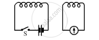
If S is kept closed, will the pointer:
(a) return to zero?
(b) stay over on the right?
(c) move to the left and stay there
(d) move to and fro until S is opened
A coil is connected to a galvanometer. When the N-pole of magnet is pushed into the coil, the galvanometer deflected to the right. What deflection, if any, is observed when:
the N-pole is removed?
A coil is connected to a galvanometer. When the N-pole of magnet is pushed into the coil, the galvanometer deflected to the right. What deflection, if any, is observed when:
the S-pole is inserted?
In the Activity shown below, how do we think the displacement of rod AB will be affected if
- current in rod AB is increased
- a stronger horse-shoe magnet is used
- length of the rod AB is increased?
|
(b) State whether the following statements are true or false:
(i) Magnetic poles exist in pairs.
(ii) Global warming is a desirable aspect of the intensified greenhouse effect.
(b) State whether the following statements are true or false:
(i) Magnetic poles exist in pairs.
Draw magnetic field lines produced around a straight current carrying conductor passing through a cardboard. How will the strength of the magnetic field change when the point where magnetic field is to be determined is moved away from the conductor?
What is that instrument which can detect the presence of electric current in a circuit?
Edison used a ______ wire coil is a vacuum glass and discovered the first electric bulb in 1879.
What are MCBs? How do they work?
An electric bell contains an ______, consisting of coils of insulated wire wound around
iron rods.
As shown in the diagram an aluminium rod 'AB' is suspended horizontally between the two poles of a strong horse shoe magnet in such a way that the axis of rod is horizontal and the direction of the magnetic field is vertically upward. The rod is connected in series with a battery and a key.
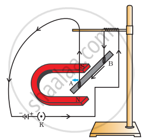
State giving reason:
- What is observed when a current is passed through the aluminium rod from end B to end A?
- What change is observed in a situation in which the axis of the rod 'AB' is moved and aligned parallel to the magnetic field and current is passed in the rod in the same direction?
Using an electromagnet, you can make a working model of a railway signal as shown in figure.

Make four electromagnets with 20, 40, 60 and 80 turns. Connect them one by one to a battery of 2 cells. Bring the electromagnet near a box of pins. Count the number of pins attracted by it. Compare the strengths of the electromagnets.
