Advertisements
Advertisements
प्रश्न
Draw the circuit diagram of a full wave rectifier using p-n junction diode.
Explain its working and show the output, input waveforms.
Advertisements
उत्तर


Full wave rectifier:
When the diode rectifies the whole of the AC wave, it is called full wave rectifier.
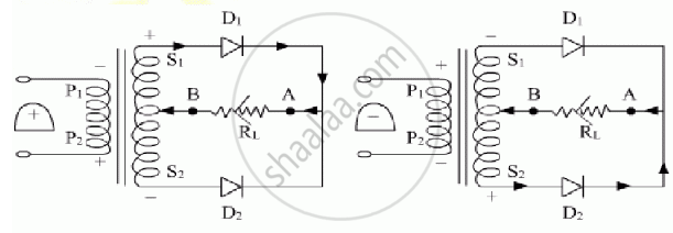
The figure shows the arrangement for using diode as full wave rectifier. The alternating input signal is fed to the primary P1P2 of a transformer. The output signal appears across the load resistance RL.
During the positive half of the input signal, suppose P1 and P2 are negative and positive respectively. This would mean that S1 and S2 are positive and negative respectively. Therefore, the diode D1 is forward biased and D2 is reverse biased. The flow of current in the load resistance RL is from A to B.
During the negative half of the input signal, S1 and S2 are negative and positive respectively. Therefore, the diode D1 is reverse biased and D2 is forward biased. The flow of current in the load resistance RL is from A to B.
