हिंदी

A series combination of an inductor (L), capacitor (C) and a resistor (R) is connected across an ac source of emf of peak value E0, and angular frequency (ω). Plot a graph to show variation of - Physics

Advertisements
Advertisements

प्रश्न

A series combination of an inductor (L), capacitor (C) and a resistor (R) is connected across an ac source of emf of peak value E0, and angular frequency (ω). Plot a graph to show variation of impedance of the circuit with angular frequency (ω).

आलेख
अति संक्षिप्त उत्तर
Advertisements

उत्तर

The graph showing the variation of impedance (Z) of the circuit with angular frequency (ω) is shown below:

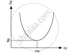
Here, ω0 represents the resonance frequency for the LCR circuit, and R is the resistance of the circuit.

shaalaa.com
  क्या इस प्रश्न या उत्तर में कोई त्रुटि है?
2019-2020 (March) Delhi Set 2

वीडियो ट्यूटोरियलVIEW ALL [2]

संबंधित प्रश्न

 A light bulb is rated at 100 W for a 220 V a.c. supply. Calculate the resistance of the bulb.


A light bulb is rated at 120 W for a 220 V a.c. supply. Calculate the resistance of the bulb.


A light bulb is rated at 125 W for a 250 V a.c. supply. Calculate the resistance of the bulb.


What is the reactance of a capacitor connected to a constant DC source?


An AC source is connected to a capacitor. Will the rms current increase, decrease or remain constant if a dielectric slab is inserted into the capacitor?


When the frequency of the AC source in an LCR circuit equals the resonant frequency, the reactance of the circuit is zero. Does it mean that there is no current through the inductor or the capacitor?


The reactance of a circuit is zero. It is possible that the circuit contains
(a) an inductor and a capacitor
(b) an inductor but no capacitor
(c) a capacitor but no inductor
(d) neither an inductor nor a capacitor


(i) An alternating emf of 200 V, 50 Hz is applied to an L-R ciruit, having a resistance R of 10 Ω and an  inductance L of 0.05H connected in series. Calculate : 

(1) Impedance

(2) Current flowing in the circuit 

(ii) Draw a labelled graph showing the variation of inductive reactance (`X_L`) verses frequency (`f`) .


The potential difference across the resistor is 160 V and that across the inductor is 120 V. Find the effective value of the applied voltage. If the effective current in the circuit is 1⋅0 A, calculate the total impedance of the circuit.


In a series RL circuit, VR = 200 V and VL = 150 V. Find the applied voltage.


Share
Notifications

Englishहिंदीमराठी


      Forgot password?
Use app×