Advertisements
Advertisements
प्रश्न
You are given three circuit elements X, Y and Z. When the element X is connected across an a.c. source of a given voltage, the current and the voltage are in the same phase. When the element Y is connected in series with X across the source, voltage is ahead of the current in phase by π/4 . But the current is ahead of the voltage in phase by π/4when Z is connected in series with X across the source. Identify the circuit elements X, Y and Z. When all the three elements are connected in series across the same source, determine the impedance of the circuit.Draw a plot of the current versus the frequency of applied source and mention the significance of this plot.
Advertisements
उत्तर
When the element X is connected across an a.c. source of a given voltage, the current is in phase with the applied voltage. This implies that the circuit element X is a resistance R.
When the circuit element Y is connected in series with X across an a.c. source, the voltage is found to lead the current by a phase angle π/4. This indicates that the circuit
element Y is an inductance L. The circuit element Z is a capacitance C as it is found that the current leads the voltage by a phase angle π/4.
When the three circuit elements—resistance, inductance and capacitance—are connected in series with the a.c. source, the impedance of the circuit is given by
`Z=sqrt(R^2+(X_L+X_C)^2`
where R is the resistance, XL is the inductive reactance and XC is the capacitive reactance
The variation of current with the changing frequency of applied voltage in a circuit in which X, Y and Z are connected in series is as shown below:
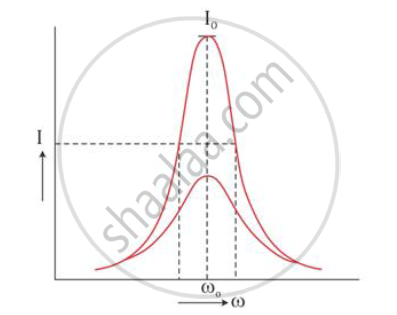
Such an LCR circuit connected in series admits maximum current corresponding to a
given frequency of a.c. This frequency is known as series resonance frequency.
At resonant frequency ω0, the impedance of the LCR circuit is minimum, and hence, the
current becomes maximum.
For frequencies greater than or less than ω0, the values of current are less than the maximum current value I0. As a series resonance circuit admits maximum peak current through it at resonance, it is called an acceptor circuit. Such circuits find application in radios, TV receiver sets etc.
