Advertisements
Advertisements
प्रश्न
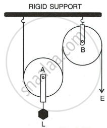
The diagram below shows a pulley arrangement.
- Name the pulleys A and B.
- In the diagram, mark the direction of tension on each strand of string.
- What is the purpose of the pulley B?
- If the tension is T, deduce the relation between
- T and E, and
- E and L.
- What is the velocity ratio of the arrangement?
- Assuming that the efficiency of the system is 100%, what is the mechanical advantage?
Advertisements
उत्तर
- Pulley A is a movable pulley.
Pulley B is a fixed pulley. - Tension T is marked in (f)
-
Pulley B's function is to reverse the direction of effort applied, moving it from upward to downward.
- Relation between:
- T and E are E = T.
- Between E and L, is E = `L/2`
- V.R. = `("Distance moved by effort" d_E)/("Distance moved by load" d_L)`
V.R. = `(2d)/d = 2` - M.A. = Efficiency × V.R.
= `100/100 xx 2 = 2`
APPEARS IN
संबंधित प्रश्न
A pulley system with VR = 4 is used to lift a load of 175 kgf through a vertical height of 15 m. The effort required is 50 kgf in the downward direction. (g = 10 N kg-1)
Calculate:
- Distance moved by the effort
- Work done by the effort
- M.A. of the pulley system
- Efficiency of the pulley system
A pulley system has three pulleys. A load of 120 N is overcome by applying an effort of 50 N. Calculate the Mechanical Advantage and Efficiency of this system.
The mechanical advantage of an actual pulley is less than one. Give a reason. What is the justification for using the pulley then?
What is a block and tackle system of pulleys?
Give reason for the following:
The lower block of a block and tackle pulley system must be of negligible weight
Give a reason for the following:
In a single fixed pulley, the velocity ratio is always more than the mechanical advantage.
A type of single pulley is very often used as a machine even though it does not give any gain in mechanical advantage. For what purpose is such a pulley used?
What is a pulley?
A ‘block and tackle’ system used 3 pulleys in the lower block and 4 pulleys in the upper block. What is the ‘velocity ratio’ of this system? If the load is to be lifted by a person capable of applying a maximum effort of 1000 N, what is the maximum load than can be lifted under ideal conditions?
The actual maximum load that gets lifted turns out to be 6300 N. What are the values of the actual M.A. and efficiency of the set-up?
