Definitions [40]
The continuous energy band formed by the merging of energy bands of each atom, known as the valence band.
A pure semiconductor in which no impurity is added intentionally.
The concentration of charge carriers in an intrinsic semiconductor, where the number of electrons equals the number of holes.
The vacancy left in the valence band when an electron leaves it behaves like a positive charge carrier in semiconductor theory.
Intrinsic semiconductors have very low conductivity at room temperature. Therefore, they are not useful for constructing electronic devices. Their electrical conductivity can be increased by adding a suitable impurity. This process is called doping.
The semiconductor to which the dopant is added is called the host.
The impurity added is called a dopant.
A doped semiconductor is called an extrinsic semiconductor or impurity semiconductor.
A p-type semiconductor is a semiconductor obtained by doping pure silicon or germanium with a trivalent impurity so that holes become the majority charge carriers.
Since every pentavalent dopant atom donates one electron for conduction, it is called a donor impurity.
With reference to a semiconductor diode, define the depletion region.
A semiconductor diode's depletion zone is the area surrounding the p-n junction where there are no mobile charge carriers, this area generates an electric field that allows the diode to conduct in one direction while blocking in another.
A semiconductor diode is a two-terminal p-n junction device that allows current to pass easily in one direction and offers high resistance in the opposite direction.
In semiconductor physics, what is meant by:
(i) rectifier
(ii) an amplifier
(iii) an oscillator
(i) Rectifier: It is a device which converts alternating current into direct current.
(ii) Amplifier: An amplifier is a device which increases the energy of a weak signal by supplying energy from an external source. An amplifier increases the amplitude of a input signal.
(iii) Oscillator: An oscillator is a device which produces electrical oscillations of adjustable frequency and constant amplitude. An oscillator is basically an amplifier. A part of the output energy is fed back into the L-C circuit to produce sustained oscillations.
With reference to a semiconductor diode, define the potential barrier.
The barrier that the repelling forces use to stop the mobile charge carriers (at the PN junction) is known as the potential barrier.
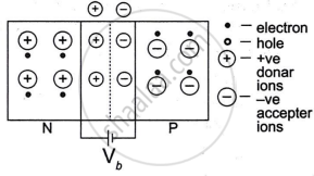
This results from the concentration of immobile charges close to the junction after electrons and holes diffuse across the function.
The process in which charge carriers move from a higher concentration to a lower concentration is called diffusion.
The ratio of voltage to current at any operating point of a diode is called static resistance.
The ratio of a small change in voltage to the corresponding small change in current is called dynamic resistance.
The boundary formed when p-type and n-type semiconductor regions are joined in a single crystal is called a p-n junction.
The region around the junction that is free from mobile charge carriers is called the depletion region.
The potential difference developed across the depletion layer due to immobile ions is called the barrier potential.
The two-terminal semiconductor device that allows current mainly in one direction is called a p-n junction diode.
The motion of charge carriers under the influence of an electric field is called drift.
The minimum forward voltage after which the current rises sharply is called the knee voltage.
The small current flowing in reverse bias due to minority carriers is called the reverse saturation current.
The reverse voltage at which the current suddenly increases rapidly is called the breakdown voltage.
When an external voltage V is applied across a semiconductor diode such that the p-type is connected to +ve terminal and n-type to -ve terminal of battery (in general p-type to high voltage and n-type to low voltage), the diode is said to be forward biased.
When an external voltage V is applied across a semiconductor diode such that the p-type is connected to the -ve terminal and n-type to the +ve terminal of the battery (in general, p-type to low voltage and n-type to high voltage), the diode is said to be reverse biased.
A basic semiconductor device that controls the flow of electric current in a circuit, which when forward biased behaves as a closed circuit and when reverse biased behaves as an open circuit, is called a p-n Junction Diode.
- The electronic circuit which rectifies AC voltage is called a Rectifier.
- The device used to convert an alternating current into a direct current is called a rectifier.
- The conversion of AC voltage into a DC voltage is called Rectification.
- The process of converting an alternating current into a direct current is called rectification.
- A rectifier that consists of one p-n junction diode in which alternate pulses of AC input are rectified, having a maximum efficiency of 40.6% and output frequency the same as that of input, is called a Half-Wave Rectifier.
- A rectifier which rectifies only one-half of each AC input supply cycle is called a half-wave rectifier.
To rectify AC power for using both half cycles of the sine wave, a different rectification circuit configuration is used, which is known as full-wave rectification.
- A rectifier that consists of two p-n junction diodes in which both the pulses of AC input are rectified, having a maximum efficiency of 81.2% and an output frequency twice that of the input, is called a Full-Wave Rectifier.
- A rectifier which rectifies both halves of each AC input cycle is called a full wave rectifier.
What is a solar cell?
It is a semiconductor device used to convert photons of solar light into electricity. It generates emf when solar radiation falls on the p-n junction. A p-type silicon wafer of about 300 μm is taken over which a thin layer of n-type silicon is grown on one side by the diffusion process.

A unique form of a bipolar device which permits the current flow in the reverse direction when the voltage applied is above a certain characteristic value called Zener voltage or breakdown voltage, most commonly used in voltage regulators to protect other semiconductor devices from fluctuations in voltage, is called a Zener Diode.
A special purpose junction diode that converts light energy into electrical current, works on the principle of the photoelectric effect, operates in reverse bias, and generates a current when exposed to light (proportional to the intensity of incident light), is called a Photodiode.
A heavily doped p-n junction diode used to operate in reverse bias is called a Zener diode.
A signal that has only two states (0 and 1) is called a Digital Signal.
A signal that has continuous values is called an Analog Signal.
A device that acts as a building block for digital circuits and performs basic logical functions that are fundamental to digital circuits is called a Logic Gate.
Formulae [12]
If hole concentration is high, then:
This is especially important for numerical problems in board examinations and entrance tests.
\[r_d=\frac{\Delta V}{\Delta I}\]
R = \[\frac {V}{I}\]
\[V_{eff}=V_b-V\]
Where:
- \[V_b\] = potential barrier voltage
- V = applied external voltage
\[I=I_e+I_h\]
Where:
- \[I_e\] = electron current
- \[I_h\] = hole current
\[V_{eff}=V_b+V\]
Where:
- \[V_b\] = potential barrier voltage
- \[V\] = applied external voltage
\[I_{Z_{max}}=\frac{P_{max}}{V_Z}\]
Where \[P_{max}\] = power dissipation capability of Zener diode.
\[R=\frac{V_{IN}-V_{OUT}}{I_Z+I_L}\]
\[I_L=\frac{V_s-V_Z}{R_s}\quad\mathrm{or}\quad I_L=I_S+I_Z\]
\[V_{OUT}=V_{IN}-I_R=V_{IN}-(I_Z+I_L)R\]
\[I=I_Z+I_L\]
| AND Gate | Y = A ⋅ B |
| OR Gate | Y = A + B |
| NOT Gate | Y = \[\overline A\] |
| NAND Gate | Y = \[\overline {AB}\] |
| NOR Gate | Y= \[\overline {(A+B)}\] |
| X-OR Gate | Y = A ⊕ B = \[\overline A\] ⋅ B + \[\overline {AB}\] |
Theorems and Laws [1]
Formation of Energy Bands
In a single isolated atom, electrons occupy discrete, well-defined energy levels (like rungs of a ladder).
When atoms are packed together in a crystal lattice, electrons are shared among neighbouring atoms. This causes:
- Each discrete energy level splits into closely spaced levels
- These closely spaced levels collectively form an energy band
Analogy: Think of a single tuning fork producing one frequency. When thousands of tuning forks are placed close together, they create a continuous range (band) of frequencies, not a single note.
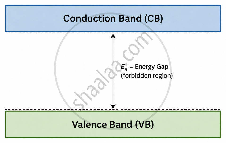
Key Energy Bands
| Band | Description |
|---|---|
| Valence Band (VB) | The highest-energy band that is completely or partially filled with electrons at 0 K. Electrons here are bound to atoms. |
| Forbidden Energy Gap (E_g) | Energy region with no allowed states. Electrons cannot exist here. Also called the Band Gap. |
| Conduction Band (CB) | Energy band above the valence band. Electrons here are free to move and conduct electricity. |
Key Points
- Solid-state materials are grouped as insulators, semiconductors, and conductors.
- Common semiconductors, silicon and germanium, have 4 outer valence electrons for bonding.
- In a pure crystal, each atom is bonded covalently to another four atoms, with its outer electrons bonded, leaving very few free electrons, making resistance very large.
- A few free electrons arise from imperfections in the crystal lattice and thermal ionisation due to heating.
- Higher temperature results in more free electrons, which increases conductivity and decreases resistance — as seen in a thermistor.
| Aspect | Conductors | Insulators | Semiconductors |
|---|---|---|---|
| Band gap | None (bands overlap) | Large (~10 eV) | Small (~1 eV) |
| Electron transition | Free movement | Not possible easily | Possible with small energy |
| Energy requirement | None | Very high | Low |
| Energy Band Structure | 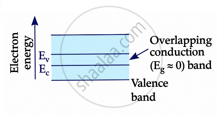 |
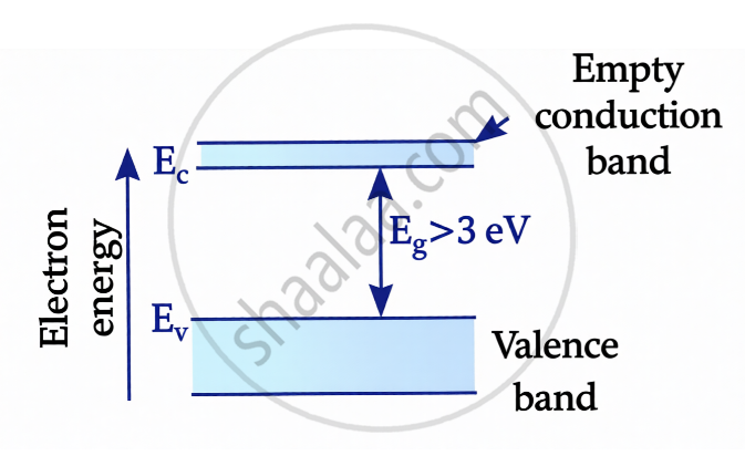 |
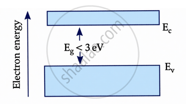 |
- In Bohr's model, electrons occupy sharp and distinct energy levels, but with many atoms interacting, these levels spread out and broaden into energy bands.
- In a silicon crystal, there are 10²³ atoms per cubic centimetre, so individual energy levels form broad energy ranges.
- Energy band diagrams of semiconductors plot energy as a function of wave number vˉvˉ along crystallographic directions, as the band diagram depends on direction in the crystal.
- Energy band diagrams contain many completely-filled and empty bands along with multiple partially-filled bands.
- When a hole moves, it is actually electrons moving in the opposite direction — the hole appears to move to the right as the electron moves to the left.
- Intrinsic semiconductors have very low conductivity at room temperature.
- Doping increases conductivity.
- A doped semiconductor is called an extrinsic semiconductor.
- The impurity added is called a dopant.
- The semiconductor receiving the impurity is called the host.
- The dopant size should be nearly the same as that of the host atom.
- Pentavalent and trivalent impurities are used as dopants.
- Extrinsic semiconductors are of two types: n-type and p-type.
- An n-type semiconductor is formed by doping silicon or germanium with a pentavalent impurity.
- Pentavalent impurities act as donor impurities.
- The fifth valence electron is weakly bound and can become free easily.
- Electrons are majority carriers and holes are minority carriers.
- For an n-type semiconductor, ne >> nh.
- Donor energy levels lie close to the conduction band.
- Extrinsic semiconductors are better conductors than intrinsic semiconductors.
- A p-n junction is formed by joining p-type and n-type semiconductor regions in a single crystal.
- Diffusion of carriers creates a depletion region and barrier potential.
- A p-n junction diode conducts mainly in one direction.
- In forward bias, the barrier potential decreases, and the current becomes large.
- In reverse bias, the barrier potential increases and only a small minority-carrier current flows.
- In zero bias, the diffusion and drift currents balance, so the net current is zero.
- The knee voltage is about 0.3 V for germanium and 0.7 V for silicon.
- Static resistance is given by R = V/I, and dynamic resistance is given by rd = ΔV/ΔI.
- In forward bias, the depletion layer becomes thin and the forward current increases strongly after the KNEE point.
- The resistance of an ideal diode in forward bias is zero.
- If external voltage (V) is greater than barrier voltage, majority carriers diffuse across the junction, constituting diffusion current \[I=I_e+I_h\].
- Knee voltage for Germanium (Ge) ≈ 0.3 V and for Silicon (Si) ≈ 0.7 V.
- Electrons and holes freely cross the junction in forward bias, leading to a diffusion current opposite to the reverse saturation current.
- As forward bias increases, the effective barrier reduces to \[V_b - V\], allowing more carriers to cross.
- In reverse bias, the current is quite small and is independent of the external voltage (until breakdown).
- The width of the depletion layer increases, and the p-n junction diode acts as a resistor.
- The width of the potential barrier increases, obstructing the flow of majority carriers in both the n-side and the p-side.
- In reverse bias, the majority charge carriers are attracted away from the depletion layer by their respective battery terminals connected to the p-n junction.
- Positive terminal attracts electrons away from the junction in the n-side; negative terminal attracts holes away from the junction in the p-side.
- Beyond a certain voltage, breakdown occurs via avalanche or Zener mechanism.
- In forward bias, the current is initially very small; it rises sharply only after the knee voltage.
- Knee voltage: Ge = 0.3 V, Si = 0.7 V (also called threshold voltage / forward voltage).
- In reverse bias, current is very low and nearly constant — measured in microamperes (μA).
- At reverse breakdown voltage, current increases sharply due to the avalanche effect.
- Avalanche effect: high-velocity electrons knock bonded electrons → chain reaction → sharp rise in current.
- The V–I graph has four regions: forward bias, knee, reverse bias, and reverse breakdown region.
- A rectifier is a circuit which converts an AC supply into a unidirectional DC supply.
- A p-n junction diode acts as a rectifier because it allows current to flow in one direction only.
- The bridge rectifier circuit uses semiconductor diodes for converting AC, as it allows current to flow in one direction only.
- Input to the rectifier is AC \[(V_{IN})\]; output is DC \[(V_{OUT})\] — shown as a full-wave rectified signal.
- Rectification is the fundamental principle behind power supply circuits in electronic devices.
- A half-wave rectifier uses a single diode, allowing current to flow in one direction, with an AC power source\[V_{ac}\] connected to the diode and a resistor in series.
- Output is discontinuous and pulsating DC - only positive half cycles appear across the load.
- Alternative (negative) half cycles of the AC supply go to waste, making efficiency very low.
- The output waveform shows only the positive side of the sinusoidal cycle, clamping off the negative side.
- Circuit components: transformer (primary & secondary), single diode, and load resistor \[R_L\].
- A transformer is used to step up or step down the AC voltage before rectification.
- A full-wave rectifier rectifies both half-cycles of the AC input; the output is continuous and pulsating.
- Two types: Centre-tap rectifier (uses 2 diodes) and Bridge rectifier (uses 4 diodes).
- The output of a full-wave rectifier is continuous but pulsating — it can be made smooth using a filter circuit.
- A large capacitor in parallel with the output load resistor reduces the ripple from the rectification process.
- Full-wave rectifiers are used in power supplies to convert AC voltages to DC voltages.
- A bridge rectifier uses no centre-tap transformer, making it more commonly used in practice.
- LED emits visible light or invisible infrared light when forward-biased.
- LEDs which emit invisible infrared light are used for remote controls.
- Types of LED materials and their colours:
- GaAs - infrared; GaAsP - red to infrared, orange
- GaP - red, yellow, green; AlGaP - green
- GaN - green, emerald green; GaInN - near ultraviolet, bluish-green, blue
- SiC - blue (as substrate); ZnSe - blue; AlGaN - ultraviolet
- AlGaAsP - high-brightness red, orange-red, orange, yellow
- The energy band diagram shows a forbidden gap between conduction and valence bands - emitted photons correspond to this gap energy.
- LED I–V characteristics show different curves for Red (R), Yellow (Y), Green (G), and Blue (B) - the higher the frequency of light, the higher the threshold voltage.
- A photodiode is specially designed to operate in reverse bias conditions.
- It conducts electric current in a similar proportion to the amount of light falling on it.
- A photodiode has two terminals - anode and cathode - with arrows indicating light rays falling on the diode.
- It is also referred to as a photo-detector, photo-sensor, or light detector.
- A photodiode works in reverse bias and is sensitive to a specific wavelength.
- It can be used as a photodetector to detect optical signals.
- Applications include: sensors, communication systems, and solar cells.
- Solar cells require no biasing — they supply emf like an ordinary cell.
- Sunlight is required for a solar cell to function.
- A solar cell is a sandwich of two different layers of silicon — the lower layer is p-type (fewer electrons), and the upper layer is n-type (more electrons).
- It contains n-type silicon and p-type silicon layers that generate electricity with sunlight by making electrons jump across the junction.
- It is compact in size and bundled with larger units for making solar panels.
- The I–V characteristics show two key parameters: \[V_{oc}\](open circuit voltage) and \[I_{sc}\] (short circuit current).
- Semiconductors with a band gap close to 1.5 eV are ideal for solar cell fabrication.
- A Zener diode is heavily doped — this causes breakdown at low reverse voltages.
- It is designed to operate in the reverse breakdown region.
- Zener diode is used as a voltage regulator.
- It is commonly used for making reference voltages and to protect electronic devices from voltage surges.
- The breakdown voltage (Zener voltage) is set during manufacturing by controlling the doping level.
- It allows current in both directions — forward like a normal diode, and reverse beyond Zener voltage.
- A Zener diode maintains a constant voltage across the load as long as the supply voltage is more than the Zener voltage.
- If the input voltage increases, the current through the Zener diode increases while the voltage drop remains constant.
- In the Zener regulator circuit,\[R_s \] is used to limit reverse current through the diode to a safer value \[V_s\], and \[R_s \] is selected so the diode operates in the breakdown region.
- When IZIZ becomes zero, IZIZ reaches its maximum value - at that case \[R=\frac{V_{IN}-V_{OUT}}{I_{Z_{max}}}\].
- Voltage regulator IC (e.g. LM7805) is a special three-terminal device: Pin 1 = \[V_{IN}\], Pin 2 = GND, Pin 3 = +5V regulated output.
- The voltage regulator has been designed to act as an ideal battery.
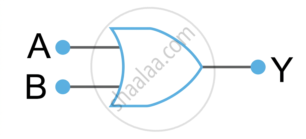
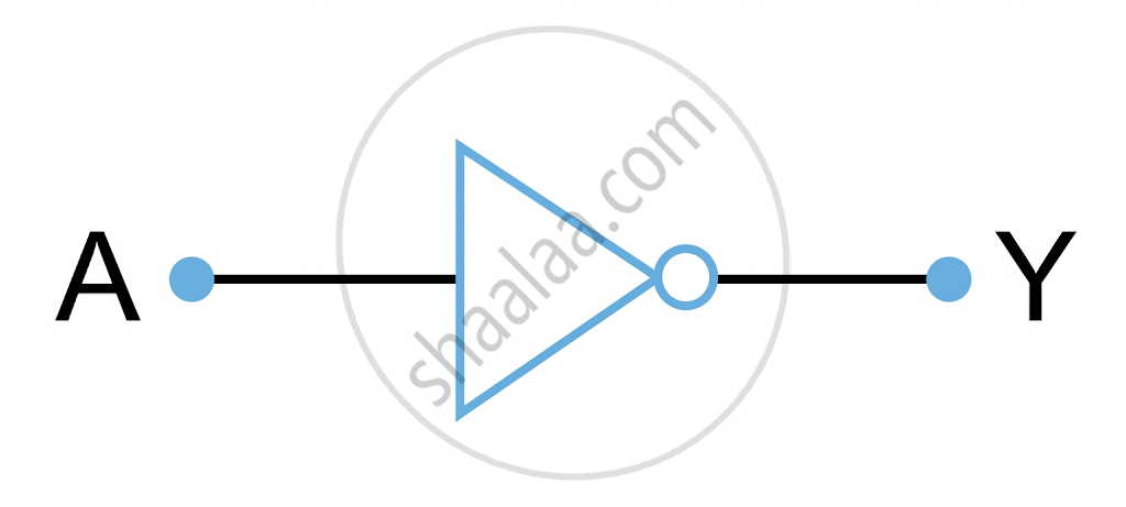
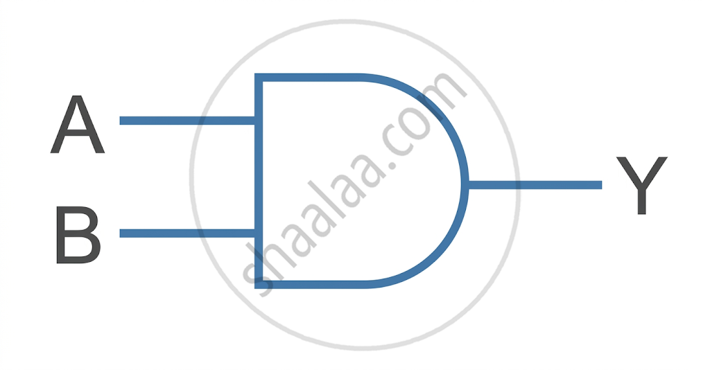
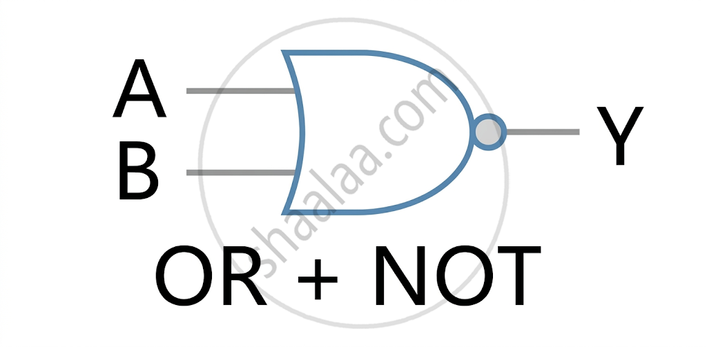
| OR GATE | NOT GATE | AND GATE | NOR GATE | NAND GATE |
|---|---|---|---|---|
 |
 |
 |
 |
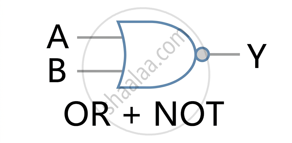 |
| 2 inputs, 1 output | 1 input, 1 output | 2 inputs, 1 output | 2 inputs, 1 output | 2 inputs, 1 output |
| Y = A + B | Y = Ā | Y = A·B | Y = (A + B)̅ | Y = (A·B)̅ |
| If any input is high, output is high | Inverted input is produced | If any input is low, output is low | When both inputs are low, output is high | When both inputs are high, output is low |
Concepts [23]
- Classification of Metals, Conductors and Semiconductors
- Semiconductor Materials
- Energy Bands in Materials
- Holes
- Intrinsic Semiconductor
- Extrinsic Semiconductor
- p-type Semiconductor
- n-type Semiconductor
- Semiconductor Diode
- Diode or p-n Junction
- Forward Bias
- Reverse Bias
- V-I Characteristics of Diode
- p-n Junction Diode as a Rectifier
- Half Wave Rectifier
- Full Wave Rectifier
- Special Purpose P-n Junction Diodes
- LED
- Photodiode
- Solar Cell
- Zener Diode
- Voltage Regulator
- Logic Gates
