Advertisements
Advertisements
प्रश्न
State whether true or false. If false, correct the statement.
Ammeter is connected in parallel in any electric circuit.
विकल्प
True
False
Advertisements
उत्तर
False
Correct Statement: An ammeter is connected in series with a device to measure its current.
APPEARS IN
संबंधित प्रश्न
Draw circuit symbols for
A closed switch
Draw the labelled diagram of an electric circuit comprising of a cell, a resistance, an ammeter, a voltmeter and a closed switch (or closed plug key). Which of the two has a large resistance : an ammeter or a voltmeter?
What do you understand by the closed electric circuit
Explain the following:
Closed circuit
Flow of electricity through a closed circuit is _____.
Draw the circuit diagram for the following series connection
Assertion: People struck by lightning receive a severe electrical shock.
Reason: Lightning carries very high voltage.
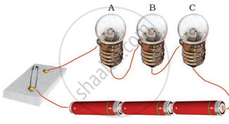
Three bulbs A, B, C are connected in a circuit as shown in the following figure. When the switch is ‘ON’
In an electric circuit a fuse is a ______ ______ to prevent possible fire.
Name the device which is used to measure the strength of the electric current in an electric circuit.
