Advertisements
Advertisements
प्रश्न
State and explain Kirchhoff’s rules.
Advertisements
उत्तर
Kirchhoff’s first rule (current rule or junction rule):
Statement: It states that the algebraic sum of the currents at any junction of a circuit is zero. It is a statement of conservation of electric charge.

Kirchhoff ’s current rule
Explanation:
All charges that enter a given junction in a circuit must leave that junction since charge cannot build up or disappear at a junction. Current entering the junction is taken as positive and current leaving the junction is taken as negative.
Applying this law to the junction A,
I1 + I2 – I3 – I4 – I5 = o
Or
I1 + I2 = + I3 I4 + I5
Kirchhoff’s second rule (voltage rule or loop rule):
Statement: It states that in a closed circuit the algebraic sum of the products of the current and resistance of each part of the circuit is equal to the total emf included in the circuit. This rule follows from the law of conservation of energy for an isolated system. (The energy supplied by the emf sources is equal to the sum of the energy delivered to all resistors).
Explanation:
The product of current and resistance is taken as positive when the direction of the current is followed. Suppose if the direction of current is opposite to the direction of the loop, then product of current and voltage across the resistor is negative. It is shown in following Fig. (a) and (b). The emf is considered positive when proceeding from the negative to the positive terminal of the cell. It is shown in following fig. (c) and (d).
(a)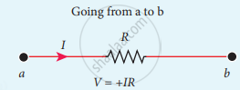
(b)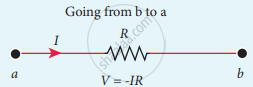
(c)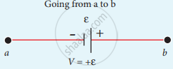
(d)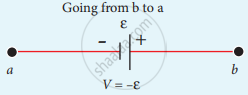
Kirchhoff voltage rule
APPEARS IN
संबंधित प्रश्न
Use Kirchhoff's rules to obtain conditions for the balance condition in a Wheatstone bridge.
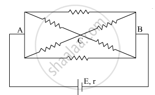
The current is drawn from a cell of emf E and internal resistance r connected to the network of resistors each of resistance r as shown in the figure. Obtain the expression for
- the current draw from the cell and
- the power consumed in the network.
State Kirchhoff's rules for an electric network. Using Kirchhoff's rules, obtain the balance condition in terms of the resistances of four arms of Wheatstone bridge.
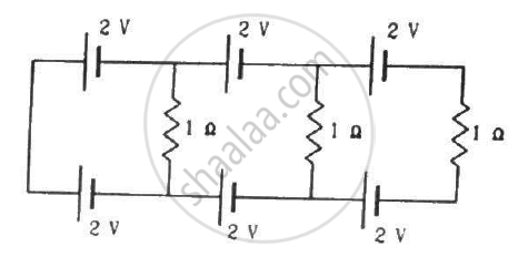
Find the circuit in the three resistors shown in the figure.
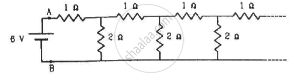
An infinite ladder is constructed with 1 Ω and 2 Ω resistors, as shown in the figure. (a) Find the effective resistance between the points A and B. (b) Find the current that passes through the 2 Ω resistor nearest to the battery.
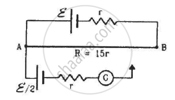
Consider the potentiometer circuit as arranged in the figure. The potentiometer wire is 600 cm long. (a) At what distance from the point A should the jockey touch the wire to get zero deflection in the galvanometer? (b) If the jockey touches the wire at a distance of 560 cm from A, what will be the current in the galvanometer?
The figure below shows two batteries, E1 and E2, having emfs of 18V and 10V and internal resistances of 1 Ω and 2 Ω, respectively. W1, W2 and W3 are uniform metallic wires AC, FD and BE having resistances of 8 Ω, 6 Ω and 10 Ω respectively. B and E are midpoints of the wires W1 and W2. Using Kirchhoff's laws of electrical circuits, calculate the current flowing in the wire W3:

What is a junction or node?
Which algebraic form is equivalent to \[I_1+I_2=I_3+I_4\]?
What is the sign of the emf when moving from the negative terminal to the positive terminal of a cell?
