Advertisements
Advertisements
प्रश्न
Explain what would happen if the capacitor given in previous question a 3 mm thick mica sheet (of dielectric constant = 6) were inserted between the plates,
- While the voltage supply remained connected.
- After the supply was disconnected.
Advertisements
उत्तर
- Dielectric constant of the mica sheet, k = 6
Initial capacitance, C = 1.771 × 10⁻¹¹ F
New Capacitance, C' = kC
= 6 × 1.771 × 10−11
= 106 pF
Supply voltage, V = 100 V
New Capacitance, q' = C'V
= 6 × 1.771 × 10−9
= 1.06 × 10⁻⁸ C
Potential across the plates remains 100 V. - Dielectric constant, k = 6
Initial capacitance, C = 1.771 × 10⁻¹¹ F
New Capacitance, C' = kC
= 6 × 1.771 × 10−11
= 106 pF
If the supply voltage is removed, then there will be no effect on the amount of charge in the plates.
Charge = 1.771 × 10⁻⁹ C
Potential across the plates comes from,
∴ `"V'" = "q"/"C'"`
= `(1.771 xx 10^-9)/(106 xx 10^-12)`
= 16.7 V
APPEARS IN
संबंधित प्रश्न
A 12 pF capacitor is connected to a 50 V battery. How much electrostatic energy is stored in the capacitor?
The energy density in the electric field created by a point charge falls off with the distance from the point charge as
A capacitor of capacitance 500 μF is connected to a battery through a 10 kΩ resistor. The charge stored in the capacitor in the first 5 s is larger than the charge stored in the next.
(a) 5 s
(b) 50 s
(c) 500 s
(d) 500 s
A capacitance C, a resistance R and an emf ε are connected in series at t = 0. What is the maximum value of (a) the potential difference across the resistor (b) the current in the circuit (c) the potential difference across the capacitor (d) the energy stored in the capacitor (e) the power delivered by the battery and (f) the power converted into heat?
A 20 μF capacitor is joined to a battery of emf 6.0 V through a resistance of 100 Ω. Find the charge on the capacitor 2.0 ms after the connections are made.
A 100 μF capacitor is joined to a 24 V battery through a 1.0 MΩ resistor. Plot qualitative graphs (a) between current and time for the first 10 minutes and (b) between charge and time for the same period.
How many time constants will elapse before the current in a charging RC circuit drops to half of its initial value? Answer the same question for a discharging RC circuit.
How many time constants will elapse before the energy stored in the capacitor reaches half of its equilibrium value in a charging RC circuit?
A capacitor of capacitance 12.0 μF is connected to a battery of emf 6.00 V and internal resistance 1.00 Ω through resistanceless leads. 12.0 μs after the connections are made, what will be (a) the current in the circuit (b) the power delivered by the battery (c) the power dissipated in heat and (d) the rate at which the energy stored in the capacitor is increasing?
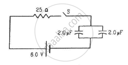
Find the charge on each of the capacitors 0.20 ms after the switch S is closed in the figure.
Consider the situation shown in figure. The switch is closed at t = 0 when the capacitors are uncharged. Find the charge on the capacitor C1 as a function of time t.
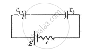
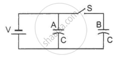
Figure shows two identical parallel plate capacitors connected to a battery through a switch S. Initially, the switch is closed so that the capacitors are completely charged. The switch is now opened and the free space between the plates of the capacitors is filled with a dielectric of dielectric constant 3. Find the ratio of the initial total energy stored in the capacitors to the final total energy stored.
A capacitor is charged by a battery and energy stored is 'U'. Now the battery is removed and the distance between plates is increased to four times. The energy stored becomes ______.
An air-filled parallel plate capacitor has a uniform electric field `overset(->)("E")` in the space between the plates. If the distance between the plates is 'd' and the area of each plate is 'A', the energy stored in the capacitor is ______
(∈0 = permittivity of free space)
A 2µF capacitor is charge to 100 volt and then its plate are connected by a conducting wire. The heat produced is:-
Prove that, if an insulated, uncharged conductor is placed near a charged conductor and no other conductors are present, the uncharged body must be intermediate in potential between that of the charged body and that of infinity.
A parallel plate capacitor (A) of capacitance C is charged by a battery to voltage V. The battery is disconnected and an uncharged capacitor (B) of capacitance 2C is connected across A. Find the ratio of total electrostatic energy stored in A and B finally and that stored in A initially.
Electrostatic energy of 4 x 10⁻⁴ J is stored in a charged 25 pF capacitor. Find the charge on the capacitor.
