Please select a subject first
Advertisements
Advertisements
Prove that the average power taking by a pure capacitor fed with a sinusoidal ac supply in a circuit is zero.
Concept: Power and Power Factor
Derive the formula for resonant frequency of the circuit with a pure capacitor in parallel with a coil having resistance and inductance. Find the expression for dynamic resistance of this parallel resonant circuit.
Concept: Series and Parallel Resonance
A resistance and a capacitor connected in series across a 250V supply draws 5A at 50Hz. When frequency is increased to 60Hz, it draws 5.8A. Find the values of R & C. Also find active power and power factor in both cases.
Concept: AC Through Resistance
A balanced 3 phase star connected load consists of three coils each consisting of R=6Ω and 𝑿𝑳= 8Ω . Determine the line current , power factor when the load is connected across 400V, 50Hz, supply
Concept: Three Phase Current Generation
Find the node voltages 𝑽𝟏,𝑽𝟐 𝒂𝒏𝒅 𝑽𝟑 and current through 0.5Ω
Concept: Three Phase Voltage Genration
Draw the phasor diagram of a single phase transformer when it is loaded with a lagging power factor load.
Concept: phasor diagrams of Single Phase Transformer
A single phase transformer has 1000 turns on the primary and 200 turns on the secondary. The no load current is 3A at a power factor of 0.2 lag and the secondary current is 280A at a power factor of 0.8 lag. Neglect R2 and X2 calculate (1) Magnetizing component and loss component of no load current. (2) primary current (3) input power factor .Draw phasor diagram showing all the currents.
Concept: Construction of Single Phase Transformer
Describe the basic principle of operation of a single phase transformer and derive the emf equation.
Concept: Working Principle of Single Phase Transformer
The OC and SC test data are given below for a single phase, 5KVA, 200V/400V, 50Hz transformer
| OC test from LV side | 200V | 1.25A | 150w |
| SC test from HV side | 20V | 12.5A | 175w |
Determine the following :-
1) Draw the equivalent circuit of the transformer referred to LV side.
2) At what load or KVA the transformer is to be operated for maximum efficiency?
3) Calculate the value of maximum efficiency.
4) Regulation of the transformer at full load 0.8power factor lagging.
Concept: OC and SC Test
Briefly explain the classification of DC machine.
Concept: Construction and Classification of Dc Machines
state and prove varigon’s theorem.
Concept: Varignon’s Theorem
Find the resultant of the force system as shown in the given figure.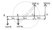
Concept: Resultant of concurrent forces
Find the resultant of the force acting on the bell crank lever shown. Also locate its position with respect to hinge B.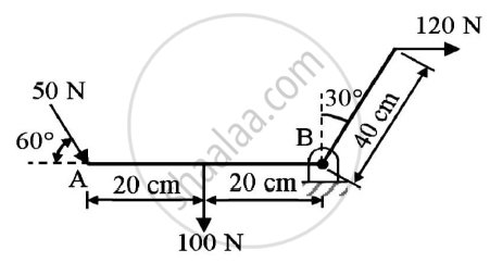
Given : Forces on the bell crank lever
To find : Resultant and it’s position w.r.t hinge B
Concept: Resultant of parallel forces
In the rocket arm shown in the figure the moment of ‘F’ about ‘O’ balances that P=250 N.Find F. 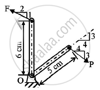
Concept: Resultant of concurrent forces
Find the force F4 , so as to give the resultant of the force as shown in the figure given below.
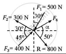
Given : Forces and their resultant
To find : Force F4
Concept: Resultant of concurrent forces
The resultant of the three concurrent space forces at A is 𝑹̅ = (-788𝒋̅) N. Find the magnitude of F1,F2 and F3 forces.
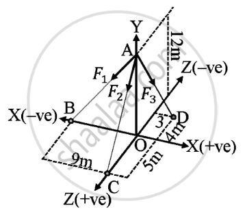
Given : A=(0,12,0)
B=(-9,0,0)
C=(0,0,5)
D=(3,0,-4)
Resultant of forces = (-788𝑗̅) N
To find : Magnitude of forces F1,F2,F3
Concept: Resultant of concurrent forces
A force of 140 kN passes through point C (-6,2,2) and goes to point B (6,6,8). Calculate moment of force about origin.
Concept: Moment of force about a point
A machine part is subjected to forces as shown.Find the resultant of forces in magnitude and in direction.
Also locate the point where resultant cuts the centre line of bar AB.
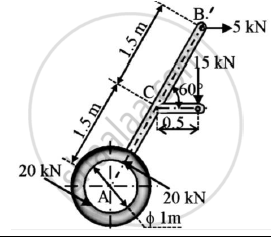
Solution:
Given : A machine subjected to various forces
To find : Resultant of forces
Point where the resultant force cuts the bar AB
Concept: Varignon’s Theorem
Find the resultant of the parallel force system shown in Figure 1 and locate the same with respect to point C.
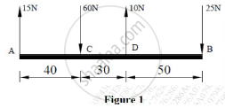
Concept: Resultant of parallel forces
A force of magnitude of 20kN, acts at point A(3,4,5)m and has its line of action passing through B(5,-3,4)m. Calculate the moment of this force about a line passing through points S(2,-5,3) m and T(-3,4,6)m.
Concept: Moment of force about a point
