Definitions [12]
Whenever there is a change in the number of magnetic field lines linked with a conductor, an electromotive force (e.mf) is developed between the ends of the conductor which lasts as long as there is a change in the number of magnetic field lines through the conductor. This phenomenon is called the electromagnetic induction.
and
Faraday's Definition:
Electromagnetic induction is the phenomenon in which an e.m.f is induced in the coil if there is a change in the magnetic flux linked with the coil.
Define the right-hand thumb rule.
If the current-carrying conductor is held in the right hand such that the thumb points in the direction of the current, then the direction of the curl of the fingers will give the direction of the magnetic field.
Whenever the number of magnetic lines of force (magnetic flux) passing through a coil changes, an electric current is induced in the coil. This current is called the induced current.
Define self-inductance.
The self-inductance of a circuit is the ratio of magnetic flux (produced due to current in the circuit) linked with the circuit to the current flowing in it.
Define the coefficient of self-induction.
It is defined as magnetic flux linked with the solenoid when unit current flows through it.
Define Mutual Inductance.
The mutual inductance M of two circuits (or coils) is the magnetic flux (Φs) linked with the secondary circuit per unit current (IP) of the primary circuit.
Define a Transformer.
The transformer is a device used for converting low voltage into high voltage and high voltage into low voltage. It works on the principle of electromagnetic induction.
Define step up and step down transformer.
Step-up transformer: The transformer used to change a low alternating voltage to a high alternating voltage is called a step-up transformer, (ie) (Vs > Vp).
Step down transformer: The transformer used to change a high alternating voltage to a low alternating voltage is called a step-down transformer (Vs < Vp).
An a.c. generator is a device which converts the mechanical energy into the electrical energy using the principle of electromagnetic induction.
Define Capacitive reactance.
The effective resistance offered by the capacitor is called capacitive reactance (ΧC).
`Χ_C = 1/omega_C`
`= 1/(2 pi fC)`
Define Impedance.
The effective opposition offered by the inductor, capacitor and resistor connected in series to flow of AC current. is called impedance.
Z = `sqrt("R"^2 + (Χ_"L" - Χ_"C")^2)`
Give any one definition of power factor.
The Power Factor is the ratio of True Power (measured in Watts) to Apparent Power (measured in Volt-Amperes) in an AC circuit.
Power factor (cos Φ) = `"True power"/"Apparent power"`
Theorems and Laws [4]
State Lenz’s Law.
It is stated that the direction of induced e.m.f. is always in such a direction that it opposes the change in magnetic flux.
e = `(d phi)/(dt)`
Consider a rectangular metal coil PQRS. Let ‘L’ be the length of the coil. It is placed in a partly magnetic field ‘B’. The direction of the magnetic field is perpendicular to the paper and into the paper. The ‘x’ part of the coil is in the magnetic field at instant t. If the coil is moved towards the right with a velocity v = dx/dt with the help of an external agent, such as a hand. The magnetic flux through the coil is:
Φ = BA = BLx
∴ Φ = BLx ...(1)
There is relative motion of a current through the coil. Let ‘i’ be current through the coil.
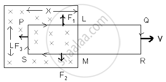
Three forces act on the coil.
F1 on conductor PL ∴ F1 = Bi x, vertically upward.
F2 on conductor MS ∴ F2 = Bi x, vertically downward.
F3 on conductor SP ∴ F3 = Bi L towards left.
F1 & F2 are equal and opposite and also on the same lines. They will cancel each other; F3 is a resultant force. The external agent has to do work against this force.
∴ F3 = −Bi l ...(−ve sign indicates that force is opposite to dx.)
If dx is the displacement in time dt, then the work done (dw) = F3 dx.
∴ dw = − BiL dx
This power is an electrical energy ‘ei’ where ‘e’ is an induced e.m.f.
∴ ei = `-(B_i ldx)/(dt)`
∴ e = `-(BLdx)/(dt)`
∴ e = −BLv
∴ e = `-d/dt (BLx)`
∴ e = `(-d phi)/(dt)` ...[from eq (1)]
Lenz’s Law states that the direction of the induced electromotive force (EMF) and the resulting current in a conductor is always such that it opposes the change in magnetic flux that caused it.
Mathematically, Lenz’s Law is expressed as:
ε = `(-d phi_B)/dt`
Where,
ε = Induced EMF
ΦB = Magnetic flux
The negative sign indicates opposition to the change in flux.
Statement:
When the magnetic flux through a circuit is changing, an induced electromotive force (emf) is set up in the circuit whose magnitude is equal to the negative rate of change of magnetic flux. This is also known as Neumann’s Law.
Mathematical Expression:
If ΔΦB is the change in magnetic flux in a time interval Δt, then the induced emf e is given by:
e = \[-\frac{\Delta\Phi_B}{\Delta t}\]
In the limiting case as Δt → 0:
e = \[-\frac{d\Phi_{B}}{dt}\]
- If dΦB is in weber (Wb) and dtdtdt in seconds (s), then the emf eee will be in volts (V).
- This equation represents an independent experimental law, which cannot be derived from other experimental laws.
For a tightly-wound coil of N turns, the induced emf becomes:
e = \[-N\frac{d\Phi_B}{dt}\] or e = \[-\frac{d(N\Phi_B)}{dt}\]
Here, NΦB is called the ‘number of magnetic flux linkages’ in the coil, and its unit is weber-turns.
Explanation:
Consider a magnet and a coil:
- When the north pole of a magnet is near a coil, a certain number of magnetic flux lines pass through the coil.
- If either the coil or the magnet is moved, the number of magnetic flux lines (i.e., the magnetic flux) through the coil changes.
Cases:
- Magnet moved away from the coil → Decrease in magnetic flux through the coil.
- Magnet brought closer to the coil → Increase in magnetic flux through the coil.
In both cases, an emf is induced in the coil during the motion of the magnet.
- Faster motion → Greater rate of change of flux → Higher induced emf.
- If both the magnet and coil are stationary, or both are moving in the same direction with the same velocity, there is no change in flux → No induced emf.
Special Case:
- If the coil is an open circuit (i.e., infinite resistance), emf is still induced, but no current flows.
- This shows that it is the change in magnetic flux that induces emf, not current.
Conclusion:
Neumann’s Law establishes that a changing magnetic flux through a circuit induces an emf, and the induced emf is proportional to the rate of change of flux, with a negative sign indicating the direction (as per Lenz’s law).
Limitations:
- The law applies to changing magnetic flux; it does not induce emf if the magnetic flux remains constant.
- No emf is induced if the coil and magnet move together at the same velocity or remain stationary.
- In open circuits, emf is induced, but no current is generated.
Statement:
The direction of the induced emf, or the induced current, in any circuit is such as to oppose the cause that produces it. This law is known as Lenz’s Law.
Explanation / Proof:
- When the north pole of a magnet is moved towards the coil, an induced current flows in the coil in such a direction that the near (left) face of the coil behaves like a north pole.
- Due to the repulsion between the like poles, the motion of the magnet towards the coil is opposed.
- When the north pole of the magnet is moved away from the coil, the induced current flows in such a direction that the near face of the coil becomes a south pole.
- The attraction between opposite poles then opposes the motion of the magnet away from the coil.
In both cases, the induced current opposes the magnet's motion, which is the cause of the current. Therefore, work has to be done to move the magnet, and this mechanical work appears as electrical energy in the coil.
Direction of Induced Current (Fleming’s Right-Hand Rule):
- Stretch the right-hand thumb, forefinger, and middle finger so that they are mutually perpendicular.
- The forefinger points in the direction of the magnetic field.
- The thumb points in the direction of motion of the conductor.
- The middle finger then gives the direction of the induced current.
Conclusion:
Lenz’s Law shows that the induced current always acts in such a direction as to oppose the cause that produces it. This ensures that mechanical energy is converted into electrical energy, and no energy is produced without work being done.
Limitations / Note:
- If the induced current were in a direction that did not oppose the motion of the magnet, electrical energy would be obtained continuously without doing any work, which is impossible.
- Hence, Lenz’s Law is consistent with the principle of conservation of energy.
Two circular loops, one of small radius r and the other of larger radius R, such that R >> r, are placed coaxially with centres coinciding. Obtain the mutual inductance of the arrangement.

Let a current IP flow through the circular loop of radius R. The magnetic induction at the centre of the loop is
BP = `(mu_0I_P)/(2R)`
As, r << R, the magnetic induction BP may be considered to be constant over the entire cross-sectional area of the inner loop of radius r. Hence magnetic flux linked with the smaller loop will be
`Φ_S = B_PA_S = (mu_0I_P)/(2R)pir^2`
Also, ΦS = MIP
∴ M = `Phi_S/I_P = (mu_0pir^2)/(2R)`
Concepts [25]
- Electromagnetic Induction
- Magnetic Flux
- The Experiments of Faraday and Henry
- Faraday's Laws of Electromagnetic Induction
- Lenz’s Law and Conservation of Energy
- Induced Current and Induced Charge
- Motional Electromotive Force (e.m.f.)
- Eddy Currents or Foucault Currents
- Inductance
- Self Inductance
- Mutual Inductance
- Transformers
- Types of Transformer
- A.C. Generator
- Representation of AC Current and Voltage by Rotating Vectors - Phasors
- Different Types of AC Circuits: AC Voltage Applied to a Resistor
- Different Types of AC Circuits: AC Voltage Applied to an Inductor
- Different Types of AC Circuits: AC Voltage Applied to a Capacitor
- Resistive-Inductive circuit (RL-circuit)
- Resistive-Capacitive circuit (RC - circuit)
- Inductive-Capacitive circuit (LC-circuit)
- Different Types of AC Circuits: AC Voltage Applied to a Series LCR Circuit
- LC Oscillations
- Power in AC Circuit
- Resonant Circuits
