Advertisements
Advertisements
प्रश्न
With the help of a circuit diagram, explain briefly how a p-n junction diode works as a half-wave rectifier.
Advertisements
उत्तर
Half-Wave rectifier: The rectifier that converts only one-half of ac into dc is called a half-wave rectifier.
Circuit diagram:

Working:
The primary coil of the transformer receives the ac input signal that needs to be rectified. A load resistance RL and a junction diode are connected in series with the secondary coil.
Point A of the secondary coil is positive and point B is at zero potential for positive ac half cycles. The junction diode is forward biassed because A is connected to the junction diode's p-region. The junction diode conducts as a result. RL is crossed to obtain the output voltage, which fluctuates in accordance with the input half cycle.
Point A is negative and point B is at zero potential for negative half cycles of ac. Since it is reverse biassed, the junction diode. As a result, there is no output across load resistance since the junction diode does not conduct.
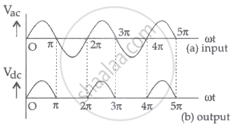
The output variation corresponding to the input is shown below:

APPEARS IN
संबंधित प्रश्न
Draw the circuit diagram of a full wave rectifier. Explain its working showing its input and output waveforms.
Draw the circuit diagram of a half wave rectifier and explain its working.
In half-wave rectification, what is the output frequency if the input frequency is 50 Hz. What is the output frequency of a full-wave rectifier for the same input frequency.
Explain with a proper diagram how an ac signal can be converted into dc (pulsating) signal with output frequency as double than the input frequency using pn junction diode. Give its input and output waveforms.
The device which uses centre-tapped secondary of the transformer is
The output of the given circuit in figure is given below.

Draw the output waveform across the resistor (Figure).
Assuming the ideal diode, draw the output waveform for the circuit given in figure. Explain the waveform.

With the help of a circuit diagram, explain how a full wave rectifier gives output rectified voltage corresponding to both halves of the input ac voltage.
Draw a labelled circuit diagram of a full wave rectifier. Show graphically how the output voltage varies with time.
