Advertisements
Advertisements
प्रश्न
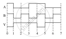
The following figure shows the input waveforms (A, B) and the output waveform (Y) of a gate. Identify the gate, write its truth table and draw its logic symbol.

Advertisements
उत्तर
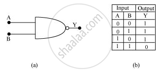
The gate is the NAND gate.

APPEARS IN
संबंधित प्रश्न
Write the truth table for the combination of the gates shown. Name the gates used.

Identify the logic gates marked 'P' and 'Q' in the given circuit. Write the truth table for the combination.

You are given two circuits as shown in following figure, which consist of NAND gates. Identify the logic operation carried out by the two circuits.
(a)

(b)

Give the truth table and circuit symbol for NAND gate
Name the logic gate which generated high output when at least one input is high.
An AND gate can be prepared by repetitive use of
(a) NOT gate
(b) OR gate
(c) NAND gate
(d) NOR gate.
You are given a circuit as shown in the figure, which consists of the NAND gate. Identify the logic operation carried out by the two. Write the truth table. Identify the gates equivalent to the tow circuit.

A radar is sending out pules of 1 micro second duration at interval of 100 micro-second. The range of the radar is
The output of 2-input or gate is zero only when its
Draw the output signals C1 and C2 in the given combination of gates (Figure).


