हिंदी
कर्नाटक बोर्ड पी.यू.सी.पीयूसी विज्ञान कक्षा ११

Figure Shows a Part of an Electric Circuit. the Wires Ab, Cd And Ef Are Long and Have Identical Resistance. The Separation Between the Neighbouring Wires is 1.0 Cm. - Physics

Advertisements
Advertisements

प्रश्न

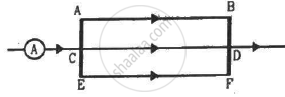
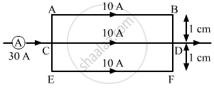
Figure shows a part of an electric circuit. The wires AB, CD and EF are long and have identical resistance. The  separation between the neighbouring wires is 1.0 cm. The wires AE and BF have negligible resistance and the ammeter reads 30 A. Calculate the magnetic force per unit length of AB and CD. 

टिप्पणी लिखिए
Advertisements

उत्तर

Since wires AB, CD and EF have identical resistance, the current (30 A) gets equally distributed in them, that is, 10 A in each wire.  

The magnetic force per unit length on a wire due to a parallel current-carrying wire is given by

\[\frac{F}{l} = \frac{\mu_0 i_1 i_2}{2\pi d}\]
∴ Magnetic force per unit length of AB = Force due to current in CD + Force due to current in EF
\[\frac{F}{l} = \frac{\mu_0 \times 10 \times 10}{2\pi \times 1 \times {10}^{- 2}} + \frac{\mu_0 \times 10 \times 10}{2\pi \times 2 \times {10}^{- 2}}\]
\[ = \frac{2 \times {10}^{- 7} \times {10}^2}{{10}^{- 2}} + \frac{2 \times {10}^{- 7} \times {10}^2}{2 \times {10}^{- 2}}\]
\[ = 2 \times {10}^{- 3} + {10}^{- 3} \]
\[ = 3 \times {10}^{- 3} \] N/m
Similarly,
Magnetic force per unit length of CD = Force due to current in AB − Force due to current in EF  
∵ Force on CD due to current in AB = Force due to current in EF  
∴ Magnetic force per unit length of CD = 0
shaalaa.com
  क्या इस प्रश्न या उत्तर में कोई त्रुटि है?
अध्याय 13: Magnetic Field due to a Current - Exercises [पृष्ठ २५१]

APPEARS IN

एचसी वर्मा Concepts of Physics Vol. 2 [English] Class 11 and 12
अध्याय 13 Magnetic Field due to a Current
Exercises | Q 29 | पृष्ठ २५१

संबंधित प्रश्न

Sketch the change in flux, emf and force when a conducting rod PQ of resistance R and length l moves freely to and fro between A and C with speed v on a rectangular conductor placed in uniform magnetic field as shown in the figure


A small compass needle of magnetic moment ‘m’ is free to turn about an axis perpendicular to the direction of uniform magnetic field ‘B’. The moment of inertia of the needle about the axis is ‘I’. The needle is slightly disturbed from its stable position and then released. Prove that it executes simple harmonic motion. Hence deduce the expression for its time period.


You are facing a circular wire carrying an electric current. The current is clockwise as seen by you. Is the field at the centre coming towards you or going away from you?


A vertical wire carries a current in upward direction. An electron beam sent horizontally towards the wire will be deflected


Two parallel wires carry currents of 20 A and 40 A in opposite directions. Another wire carying a current anti parallel to 20 A is placed midway between the two wires. T he magnetic force on it will be


A wire of length l carries a current i long the x-axis. A magnetic field exists, which is given as `vecB = B_0 (veci + vecj + veck)`  T. Find the magnitude of the magnetic force acting on the wire.


A current of 5.0 A exists in the circuit shown in the figure. The wire PQ has a length of 50 cm and the magnetic field in which it is immersed has a magnitude of 0.20 T. Find the magnetic force acting on the wire PQ.


A rigid wire consists of a semi-circular portion of radius R and two straight sections (figure). The wire is partially immersed in a perpendicular magnetic field B, as shown in the figure. Find the magnetic force on the wire if it carries a current i.


Consider a non-conducting plate of radius r and mass m that has a charge q distributed uniformly over it. The plate is rotated about its axis with an angular speed ω. Show that the magnetic moment µ and the angular momentum l of the plate are related as `mu = q/(2 m)l`


Consider a solid sphere of radius r and mass m that has a charge q distributed uniformly over its volume. The sphere is rotated about its diameter with an angular speed ω. Show that the magnetic moment µ and the angular momentum l of the sphere are related as `mu = q/(2m) l`


A long wire carrying a current i is bent to form a place along α . Find the magnetic field B at a point on the bisector of this angle situated at a distance x from the vertex.


A long, straight wire is fixed horizontally and carries a current of 50.0 A. A second wire having linear mass density 1.0 × 10⁻⁴ kg m−1 is placed parallel to and directly above this wire at a separation of 5.0 mm. What current should this second wire carry such that the magnetic repulsion can balance its weight? 


Two infinitely long current carrying conductors X and Y are kept parallel to each other, 24 cm apart in a vacuum. They carry currents of 5A and 7A respectively, in the same direction, as shown in the figure below. Find the position of a neutral point, i.e., a point where resultant magnetic flux density is zero. (Ignore earth’s magnetic field). 


A straight horizontal conducting rod of length 0.45 m and mass 60 g is suspended by two vertical wires at its ends. A current of 5.0 A is set up in the rod through the wires.

(a) What magnetic field should be set up normal to the conductor in order that the tension in the wires is zero?

(b) What will be the total tension in the wires if the direction of current is reversed keeping the magnetic field same as before?
(Ignore the mass of the wires) g = 9.8 m s–2.


Correct expression for force on a current carrying conductor of length dl in a magnetic field is ______.


A charged particle is moving on circular path with velocity v in a uniform magnetic field B, if the velocity of the charged particle is doubled and strength of magnetic field is halved, then radius becomes ______.


A straight conductor of length 2m moves at a speed of 20 m/s. When the conductor makes an angle of 30° with the direction of magnetic field of induction of 0.1 wbm2 then induced emf:


A conducting ring of radius 1m kept in a uniform magnetic field B of 0.01 T, rotates uniformly with an angular velocity 100 rad s−1 with its axis of rotation perpendicular to B. The maximum induced emf in it is:


Share
Notifications

Englishहिंदीमराठी


      Forgot password?
Use app×