Advertisements
Advertisements
प्रश्न
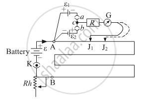
A student uses the circuit diagram of a potentiometer as shown in the figure
(a) for a steady current I passing through the potentiometer wire, he gets a null point for the cell ε1. and not for ε2. Give the reason for this observation and suggest how this difficulty can be resolved.
(b) What is the function of resistance R used in the circuit? How will the change in its value affect the null point?
(c) How can the sensitivity of the potentiometer be increased?
Advertisements
उत्तर
(a) To get a null point on the potentiometer scale, the positive terminal of the battery should be connected at zero end A. If the cell is attached with opposite terminals, i.e. negative terminal of the cell is connected to zero ends A, then the null point is not obtained on the potentiometer wire. In the given case, cell ε2, is connected with reverse polarity, i.e. positive terminal of the cell is not connected to zero ends A, hence the null point for ε2 is not obtained by the student on the potentiometer wire. This issue can be resolved if the polarity of the cell ε2 is reversed and the positive terminal of the cell is connected to zero end A of the potentiometer wire. In that case, the student will be able to find the null point for ε2 as well.
(b) The function of resistance R is to prevent high current flow through the wires of the sensitive potentiometer. Because initially there is high current in galvanometer and to protect galvanometer from burning we add high resistance in series. Changing the value of the resistance R will not affect the null point, as a null point is obtained when there is no current flowing through the galvanometer, hence there will not be any effect at the null point.
(c) The sensitivity of the potentiometer can be increased by decreasing its potential gradient (V/l). Which can be achieved by increasing the length of potentiometer wire.
