Advertisements
Advertisements
प्रश्न
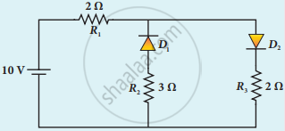
The given circuit has two ideal diodes connected as shown in the figure below. Calculate the current flowing through the resistance R1.

Advertisements
उत्तर
D1 will act as Reverse bias so current will not pass through it
Total Resistance = 4Ω
V = 10 V
Current flow through R1I = `"V"/"R"`
= `10/4`
= 2.5 A
APPEARS IN
संबंधित प्रश्न
In an unbiased p-n junction, the majority of charge carriers (that is, holes) in the p-region diffuse into the n-region because of
The zener diode is primarily used as ____________.
Which one of the following represents forward bias diode?
A diode is called a unidirectional device. Explain.
Mention the types of biasing.
Draw the circuit diagram of a half wave rectifier and explain its working.
Explain the formation of depletion region and barrier potential in PN junction diode.
Explain the working principle of a solar cell. Mention its applications.
Four silicon diodes and a 10 Ω resistor are connected as shown in the figure below. Each diode has a resistance of 1 Ω. Find the current flows through the 10 Ω resistor.

In the given figure of a voltage regulator, a Zener diode of breakdown voltage 10 V is employed. Determine the current through the load resistance, the total current and the current through the diode. Use diode approximation.

