Advertisements
Advertisements
प्रश्न
The Figure below shows an infinitely long metallic wire YY' which is carrying a current I'.
P is a point at a perpendicular distance r from it.
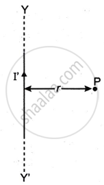
- What is the direction of magnetic flux density B of the magnetic field at the point P?
- What is the magnitude of magnetic flux density B of the magnetic field at the point P?
- Another metallic wire MN having length l and carrying a current I is now kept at point P. If the two wires are in vacuum and parallel to each other, how much force acts on the wire MN due to the current I' flowing in the wire YY'?
Advertisements
उत्तर
(i) The magnetic flux density B at point P will be directed perpendicularly inside the paper plane according to right-hand palm rule no. 2.
(ii) `B = ("μ"_0I)/(4pi) ⋅ (2I)/r`
(iii) `F = ("μ"_0)/(4pi) ⋅ (2II)/(r) xx l` (l is the length of the wire)
APPEARS IN
संबंधित प्रश्न
A square loop MNOP of side 20 cm is placed horizontally in a uniform magnetic field acting vertically downwards as shown in the figure. The loop is pulled with a constant velocity of 20 cm s−1 till it goes out of the field.
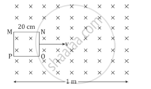
(i) Depict the direction of the induced current in the loop as it goes out of the field. For how long would the current in the loop persist?
(ii) Plot a graph showing the variation of magnetic flux and induced emf as a function of time.
A pair of adjacent coils has a mutual inductance of 1.5 H. If the current in one coil changes from 0 to 20 A in 0.5 s, what is the change of flux linkage with the other coil?
A rectangular coil having 60 turns and area of 0.4m2 is held at right angles to a uniform magnetic field of flux density 5 × 10⁻⁵T. Calculate the magnetic flux passing through it.
The unit of magnetic flux in SI is ______
A loop, made of straight edges has six corners at A(0, 0, 0), B(L, O, 0) C(L, L, 0), D(0, L, 0) E(0, L, L) and F(0, 0, L). A magnetic field `B = B_o(hati + hatk)`T is present in the region. The flux passing through the loop ABCDEFA (in that order) is ______.
A coil is placed in a time varying magnetic field. If the number of turns in the coil were to be halved and the radius of wire doubled, the electrical power dissipated due to the current induced in the coil would be: (Assume the coil to be short circuited.)
What does \[\vec A\] represent in the magnetic flux formula?
What does \[A\] represent in \[\Phi_B=BA\cos\theta\]?
When is magnetic flux maximum relative to the plane of the surface?
What happens to magnetic flux when magnetic field \[B\] increases while area and orientation remain unchanged?
