Advertisements
Advertisements
प्रश्न
Explain the construction and working of a full-wave rectifier.
Advertisements
उत्तर
Full-wave rectifier: The positive and negative half cycles of the AC input signal pass through the full-wave rectifier circuit and hence it is called the full-wave rectifier. It consists of two p-n junction diodes, a center-tapped transformer, and a load resistor (RL). The center is usually taken as the ground or zero voltage reference point. Due to the center tap transformer, the output voltage rectified by each diode is only one-half of the total secondary voltage.

Full-wave rectifier circuit

Input and output waveforms
During positive half cycle:
When the positive half cycle of the ac input signal passes through the circuit, terminal M is positive, G is at zero potential and N is at negative potential. This forward biases diode D1 and reverse biases diode D2. Hence, being forward biased, diode D1 conducts and current flows along the path MD1 AGC. As a result, the positive half cycle of the voltage appears across RL in the direction G to C.
During negative half cycle:
When the negative half cycle of the ac input signal passes through the circuit, terminal N is positive, G is at zero potential and M is at negative potential. This forward biases diode D2 and reverse biases diode D1. Hence, being forward biased, diode D2 conducts and current flows along the path ND2 BGC. As a result, the negative half cycle of the voltage appears across RL in the same direction from G to C.
Hence in a full-wave rectifier both positive and negative half cycles of the input signal pass through the circuit in the same direction as shown in the figure. Though both positive and negative half cycles of ac input are rectified, the output is still pulsating in nature. The efficiency (η) of a full-wave rectifier is twice that of a half-wave rectifier and is found to be 81.2%. It is because both the positive and negative half cycles of the ac input source are rectified.
APPEARS IN
संबंधित प्रश्न
If a positive half-wave rectified voltage is fed to a load resistor, for which part of a cycle there will be current flow through the load?
A diode is called a unidirectional device. Explain.
What do you mean by leakage current in a diode?
Draw the input and output waveforms of a full wave rectifier.
Write a short note on diffusion current across the p-n junction.
Draw the circuit diagram of a half wave rectifier and explain its working.
What is an LED? Give the principle of its operation with a diagram.
Write notes on the photodiode.
Explain the working principle of a solar cell. Mention its applications.
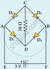
Four silicon diodes and a 10 Ω resistor are connected as shown in the figure below. Each diode has a resistance of 1 Ω. Find the current flows through the 10 Ω resistor.