Advertisements
Advertisements
प्रश्न
The Figure below shows a potentiometer circuit in which the driver cell D has an emf of 6 V and internal resistance of 2 Ω. The potentiometer wire AB is 10 m long and has a resistance of 28 Ω. The series resistance RS is of 2 Ω.

- The current Ip flowing in the potentiometer wire AB when the jockey (J) does not touch the wire AB.
- emf of the cell X if the balancing length AC is 4.5 m.
Advertisements
उत्तर
- Resistance of 10 m wire AB = 28 Ω
Rs = 20 Ω
r = 2 Ω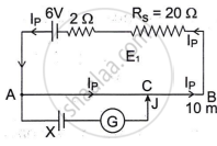
∴ Total resistance (R) = (28 + 20 + 2) Ω = 50 Ω
`I_p = V/R`
= `6/50 A`
= 0.12 A - VAB = IP × RAB
= 0.12 × 28 V
= 3.36 V
emf of cell `X = Kl ...(("Here" K = 3.36/10 Vm^-1 = 0.336 Vm^-1),(and l = 4.5 m))`
X = 0.336 × 4.5 V
X = 1.512 V
APPEARS IN
संबंधित प्रश्न
State the uses of a potentiometer.
What will be the effect on the position of zero deflection if only the current flowing through the potentiometer wire is increased?
A potential drop per unit length along a wire is 5 × 10⁻³ V/m. If the emf of a cell balances against length 216 cm of this potentiometer wire, find the emf of the cell.
When the null point is obtained in the potentiometer, the current is drawn from the ______
If the potential gradient of a wire decreases, then its length ______
A voltmeter has a resistance of 100 Ω. What will be its reading when it is connected across a cell of emf 6 V and internal resistance 20 Ω?
A cell of e.m.f. 'E' is connected across a resistance 'R'. The potential difference across the terminals of the cell is 90% ofE. The internal resistance of the cell is ______.
In a potentiometer experiment, for measuring internal resistance of a cell, the balance point has been obtained on the fourth wire. The balance point can be shifted to fifth wire by ______.
Specific resistance of a conductor increase with.
While doing an experiment with potentiometer (Figure) it was found that the deflection is one sided and (i) the deflection decreased while moving from one end A of the wire to the end B; (ii) the deflection increased. while the jockey was moved towards the end B.
- Which terminal + or – ve of the cell E1, is connected at X in case (i) and how is E1 related to E?
- Which terminal of the cell E1 is connected at X in case (ii)?

