Advertisements
Advertisements
प्रश्न
Describe how a potentiometer is used to compare the EMFs of two cells by connecting the cells individually.
Advertisements
उत्तर १
A stable emf E battery is used to create a potential gradient V/L along a potentiometer wire, where V ≡ potential difference across the length L of the wire.
The positive terminals of the cells, whose emf's (E1 and E2) are to be compared, are connected to the high potential terminal A. A two-way key connects the negative terminals of the cells to a galvanometer G. The galvanometer's other end is attached to a pencil jockey. The emf E must be greater than the emfs E1 and E2.

Comparison of two emf's using a potentiometer by the direct method
The cell with emf E1 is brought into the circuit by connecting points P and C.
The jockey is tapped along the wire to find the null point D, which is located at a distance of l1 from A. Then,
E1 = `l_1("V"/"L")`
w, without changing the potential gradient (i.e., without changing the rheostat setting) point Q (instead of P) is connected to C, bringing the cell with emf E2 into the circuit. Let its null point D' be at a distance l2 from A, so that
E2 = `l_2("V"/"L")`
As a result, `"E"_1/"E"_2` can be calculated by measuring the corresponding null lengths l1 and l2. Using the rheostat, the experiment is repeated for different potential gradients.
उत्तर २
- A potentiometer circuit is set up by connecting a battery of emf (E), with a key (K) and a rheostat such that point A is at a higher potential than point B.
- The cells whose EMFs are to be compared are connected with their positive terminals at point A and negative terminals to the extreme terminals of a two-way key K1 and K2.
- The central terminal of the two ways key is connected to a galvanometer. The other end of the galvanometer is connected to a jockey (J).

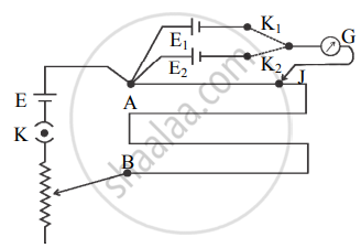
- Key K is closed and then, key K1 is closed and key K2 is kept open. Therefore, the cell of emf E1 comes into the circuit.
- The null point is obtained by touching the jockey at various points on the potentiometer wire AB.
- Let l1 be the length of the wire between the null point and point A.
Here, l1 corresponds to emf E1 of the cell. Therefore,
E1 = K l1 ….(1)
where K is the potential gradient along the potentiometer wire. - Now key K1 is kept open and key K2 is closed. The cell of emf E2 now comes in the circuit. Again, the null point is obtained with the help of the Jockey.
- Let l2 be the length of the wire between the null point and point A.
Here l2 corresponds to the emf E2 of the cell.
∴ E2 = K l2 ….(2) - Dividing equation (1) by equation (2),
`"E"_1/"E"_2 = "l"_1/"l"_2`
Thus, the EMFs of the two cells can be compared and if any one of the EMFs is known, the other can be determined.
संबंधित प्रश्न
State the principle of working of a potentiometer.
Figure shows a potentiometer with a cell of 2.0 V and internal resistance 0.40 Ω maintaining a potential drop across the resistor wire AB. A standard cell which maintains a constant emf of 1.02 V (for very moderate currents up to a few mA) gives a balance point at 67.3 cm length of the wire. To ensure very low currents drawn from the standard cell, very high resistance of 600 kΩ is put in series with it, which is shorted close to the balance point. The standard cell is then replaced by a cell of unknown emf ε and the balance point found similarly, turns out to be at 82.3 cm length of the wire.

(a) What is the value ε?
(b) What purpose does the high resistance of 600 kΩ have?
(c) Is the balance point affected by this high resistance?
(d) Is the balance point affected by the internal resistance of the driver cell?
(e) Would the method work in the above situation if the driver cell of the potentiometer had an emf of 1.0 V instead of 2.0 V?
(f) Would the circuit work well for determining an extremely small emf, say of the order of a few mV (such as the typical emf of a thermo-couple)? If not, how will you modify the circuit?
State the underlying principle of a potentiometer ?
In the given circuit in the steady state, obtain the expressions for (a) the potential drop (b) the charge and (c) the energy stored in the capacitor, C.

In the figure a long uniform potentiometer wire AB is having a constant potential gradient along its length. The null points for the two primary cells of emfs ε1 and ε2 connected in the manner shown are obtained at a distance of 120 cm and 300 cm from the end A. Find (i) ε1/ ε2 and (ii) position of null point for the cell ε1.
How is the sensitivity of a potentiometer increased?

The net resistance of a voltmeter should be large to ensure that ______________ .
The potentiometer wire AB shown in the figure is 40 cm long. Where should the free end of the galvanometer be connected on AB, so that the galvanometer may show zero deflection?

The potentiometer wire AB shown in the figure is 50 cm long. When AD = 30 cm, no deflection occurs in the galvanometer. Find R.

A battery of emf 4 volt and internal resistance 1 Ω is connected in parallel with another battery of emf 1 V and internal resistance 1 Ω (with their like poles connected together). The combination is used to send current through an external resistance of 2 Ω. Calculate the current through the external resistance.
A potentiometer wire has a length of 1.5 m and a resistance of 10 Ω. It is connected in series with the cell of emf 4 Volt and internal resistance 5 Ω. Calculate the potential drop per centimeter of the wire.
The resistance of a potentiometer wire is 8 Ω and its length is 8 m. A resistance box and a 2 V battery are connected in series with iL What should be the resistance in the box if it is desired to have a potential drop of 1 µV/mm?
The SI unit of the potential gradient is ______
When the null point is obtained in the potentiometer, the current is drawn from the ______
State any one use of a potentiometer.
A voltmeter has a resistance of 100 Ω. What will be its reading when it is connected across a cell of emf 6 V and internal resistance 20 Ω?
What are the disadvantages of a potentiometer over a voltmeter?
Two cells having unknown emfs E1 and E2 (E1 > E2) are connected in potentiometer circuit, so as to assist each other. The null point obtained is at 490 cm from the higher potential end. When cell E2 is connected, so as to oppose cell E1, the null point is obtained at 90 cm from the same end. The ratio of the emfs of two cells `("E"_1/"E"_2)` is ______.
The resistance of the potentiometer wire should ideally be ____________.
In a potentiometer experiment, when the galvanometer shows no deflection, then no current flows through ____________.
The resistivity of potentiometer wire is 40 × 10-8 ohm - metre and its area of cross-section is 8 × 10⁻⁶ m2. If 0.2 ampere current is flowing through the wire, the potential gradient of the wire is ______.
A potentiometer is an ideal device for measuring potential difference because ______.
Two cells when connected in series are balanced on 8 m on a potentiometer. If the cells are connected with polarities of one of the cell reversed, they balance on 2 m. The ratio of e.m.f's of the two cells is ____________.
A potentiometer wire has length L For given cell of emf E, the balancing length is `"L"/3` from 3 the positive end of the wire. If the length of the potentiometer wire is increased by 50%, then for the same cell, the balance point is obtained at length.
The length of a potentiometer wire is L. A cell of e.m.f E is balanced at length L/3 from the positive end of the wire. If the length of wire increases by L/2, then the same cell will give balance point at length ____________.
If the e.m.f of a cell is not constant in the metre bridge experiment, then the ____________.
A cell of e.m.f. 'E' is connected across a resistance 'R'. The potential difference across the terminals of the cell is 90% ofE. The internal resistance of the cell is ______.
A potentiometer wire of length 100 cm has a resistance of 10 `Omega.` It is connected in series with a resistance and an accumulator of e.m.f 2 V and of negligible internal resistance. A source of e.m.f 10 mV is balanced against a 40 cm length of the potentiometer wire. The value of the external resistance is ____________.
A potentiometer wire of length 100 cm and resistance 3 `Omega` is connected in series with resistance of 8 `Omega` and an accumulator of 4 volt whose internal resistance is 1 `Omega`.
The current drawn from the battery in the given network is ______
(Internal resistance of the battery is neglected)
In the experiment to determine the internal resistance of a cell (E1) using a potentiometer, the resistance drawn from the resistance box is 'R'. The potential difference across the balancing length of the wire is equal to the terminal potential difference (V) of the cell. The value of internal resistance (r) of the cell is ______
A potentiometer wire has a length of 4m and resistance of 5Ω. It is connected in series with 495 Ω resistance and a cell of e.m.f. 4V. The potential gradient along the wire is ______
A potentiometer wire is 4 m long and a potential difference of 3 V is maintained between the ends. The e.m.f. of the cell which balances against a length of 100 cm of the potentiometer wire is ______
A potentiometer wire of length 'L' and a resistance 'r' are connected in series with a battery of E.M.F. 'E0' and a resistance 'r1'. A cell of unknown E.M.F, 'E' is balanced at a length 'ℓ' of the potentiometer wire. The unknown E.M.F. E is given by ______
Potentiometer measures the potential difference more accurately than a voltmeter, because ______.
In a potentiometer experiment, for measuring internal resistance of a cell, the balance point has been obtained on the fourth wire. The balance point can be shifted to fifth wire by ______.
It is observed in a potentiometer experiment that no current passes through the galvanometer when the terminals of the cell are connected across a certain length of the potentiometer wire. On shunting the cell by a 2 Ω resistance, the balancing length is reduced to half. The internal resistance of the cell is ______.
The sensitivity of the potentiometer can be increased by ______.
In a potentiometer of 10 wires, the balance point is obtained on the 7th wire. To shift the balance point to 9th wire, we should ______.
What is the current I in the circuit as show in fig.

Specific resistance of a conductor increase with.
In a potentiometer circuit, a cell of EMF 1.5 V gives balance point at 36 cm length of wire. If another cell of EMF 2.5 V replaces the first cell, then at what length of the wire, the balance point occurs?
Consider a simple circuit shown in figure
stands for a variable resistance R′. R′ can vary from R0 to infinity. r is internal resistance of the battery (r << R << R0).

- Potential drop across AB is nearly constant as R ′ is varied.
- Current through R′ is nearly a constant as R ′ is varied.
- Current I depends sensitively on R′.
- `I ≥ V/(r + R)` always.
Potential difference between the points A and B in the circuit shown is 16 V, then potential difference across 2Ω resistor is ______ V. volt. (VA > VB)

A Daniel cell is balanced on 125 cm lengths of a potentiometer wire. Now the cell is short circuited by a resistance 2 Ω and the balance is obtained at 100 cm. The internal resistance of the Daniel cell is ______.
If you are provided a set of resistances 2Ω, 4Ω, 6Ω and 8Ω. Connect these resistances so as to obtain an equivalent resistance of `46/3`Ω.
What is the effect of decreasing the current through the potentiometer on the null point?
The Figure below shows a potentiometer circuit in which the driver cell D has an emf of 6 V and internal resistance of 2 Ω. The potentiometer wire AB is 10 m long and has a resistance of 28 Ω. The series resistance RS is of 2 Ω.

- The current Ip flowing in the potentiometer wire AB when the jockey (J) does not touch the wire AB.
- emf of the cell X if the balancing length AC is 4.5 m.
