Topics
- OR Gate
- AND Gate
- NOT gate
- NOR Gate
- NAND Gate
- EX-OR Gate
Notes
OR Gate
This gate is known as ''Inclusive - OR' gate. Consider A and B are the inputs and Y is the output. The gate is called any or all gate.
Logic- "If A is true or Bis true then Y is true"
Symbol:

Truth Table:
|
A |
B |
Y |
|
0 |
0 |
0 |
|
0 |
1 |
1 |
|
1 |
0 |
1 |
|
1 |
1 |
1 |
Boolean Equation- Y= A+ B '+'sign indicates OR function
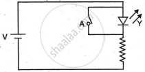
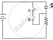
Simple Circuit:
Let us construct using A and B as switches. For the output, a lamp or LED can be used.
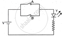
This is the circuit of OR Gate. LED will glow or current will flow, when one or both of A and B is closed.
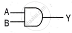
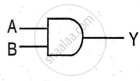
AND Gate
This is another basic logic gate, logic is different than OR logic
Logic - "If A is true and B is true then Y is true"
It means that the output of AND gate is high only when both inputs are high.
Symbol
Truth Table
|
A |
B |
Y |
|
0 |
0 |
0 |
|
0 |
1 |
0 |
|
1 |
0 |
0 |
|
1 |
1 |
1 |
Boolean equation- Y= `A•B` or Y =AB Dot indicates an AND operation.
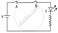
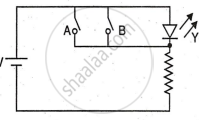
Simple Circuit: In this logic, switch A and switch B are connected in series, so that LED glows only when both are closed; otherwise, when any one switch is open, the circuit becomes an open circuit.
NOT gate
This gate is always a single input gate. It inverts the input in the output therefore known as "inverter''.
Logic - " If A is "true then Y is false and if A is false then Y is true".
Symbol:
Truth Table
|
A |
Y |
|
1 |
0 |
|
0 |
1 |
Boolean Equation: Y= `Ā ` Bar represents inversion.
Simple Circuit: To invert logic, connect a switch across the LED. When the switch is closed, the LED is shorted and turns off. When the switch is open, the short circuit is removed, current flows through the LED, and it turns on.
NOR Gate
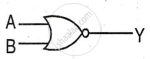
This is the complement of OR gate. If the logic of OR is inverted, then it is known as (NOT OR) or NOR gate. The gate is called nothing all gate.
Logic - "If A is true or Bis true then Y is false.'
Symbol
Truth Table
|
A |
B |
Y |
|
0 |
0 |
1 |
|
0 |
1 |
0 |
|
1 |
0 |
0 |
|
1 |
1 |
0 |
Boolean equation:
Y= `bar (A+B)`
because + sign indicates OR and bar is inversion of OR
Simple Circuit: Refer the circuit of OR and NOT, OR is a parallel circuit of switches but it is in series with lamp. It gets inverted if this parallel switch circuit is connected across the lamp. Because across the lamp means NOT circuit.
NAND Gate
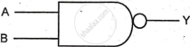
This is the complement of NAND gate. If the logic of AND is inverted, then it is known as (NOT AND) or NAND gate.
Logic - "If A is high and B is high then Y is false"
Symbol
Truth Table
|
A |
B |
Y |
|
0 |
0 |
1 |
|
0 |
1 |
1 |
|
1 |
0 |
1 |
|
1 |
1 |
0 |
Boolean equation
Y= `bar (A•B)`
Simple Circuit: Refer the circuit of AND and NOT, AND is a series circuit of switches but it is in series with lamp. It gets inverted if this series switch circuit is connected across the lamp. Because across the lamp means NOT circuit.
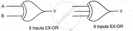
EX-OR Gate
The Exclusive OR (XOR) gate, also known as the "any but not all" gate, outputs low when both inputs are alike(same), unlike an inclusive OR gate which outputs high on both inputs high.
Logic - "When A is true OR B is true but not both, then Y is true. "
Symbol
Truth Table
|
A |
B |
Y |
|
0 |
0 |
0 |
|
0 |
1 |
1 |
|
1 |
0 |
1 |
|
1 |
1 |
0 |
Boolean Expression:
Y= `A⊕B` = `bar(A)B + Abar(B)`
Simple Circuit:

Fig. (2.7) shows the logic circuit diagram of an XOR gate using AND, OR, and NOT gates, and its equivalent SPDT switch circuit. The lamp glows when inputs are unequal (A=0, B=1 or A=1, B=0), and does not glow when inputs are equal (A=0, B=0 or A=1, B=1), demonstrating XOR operation.
ODD/EVEN Parity: An XOR gate is useful for parity checking. For two inputs, the truth table is straightforward. With an odd number of inputs, the output is high when the number of high inputs is odd, and low when even. This makes the XOR gate effective for indicating even or odd parity in data.
